The first thing I worked on was a stand for charging drops and testing if I could sense the charge somehow to start the work on the charging system from scratch.
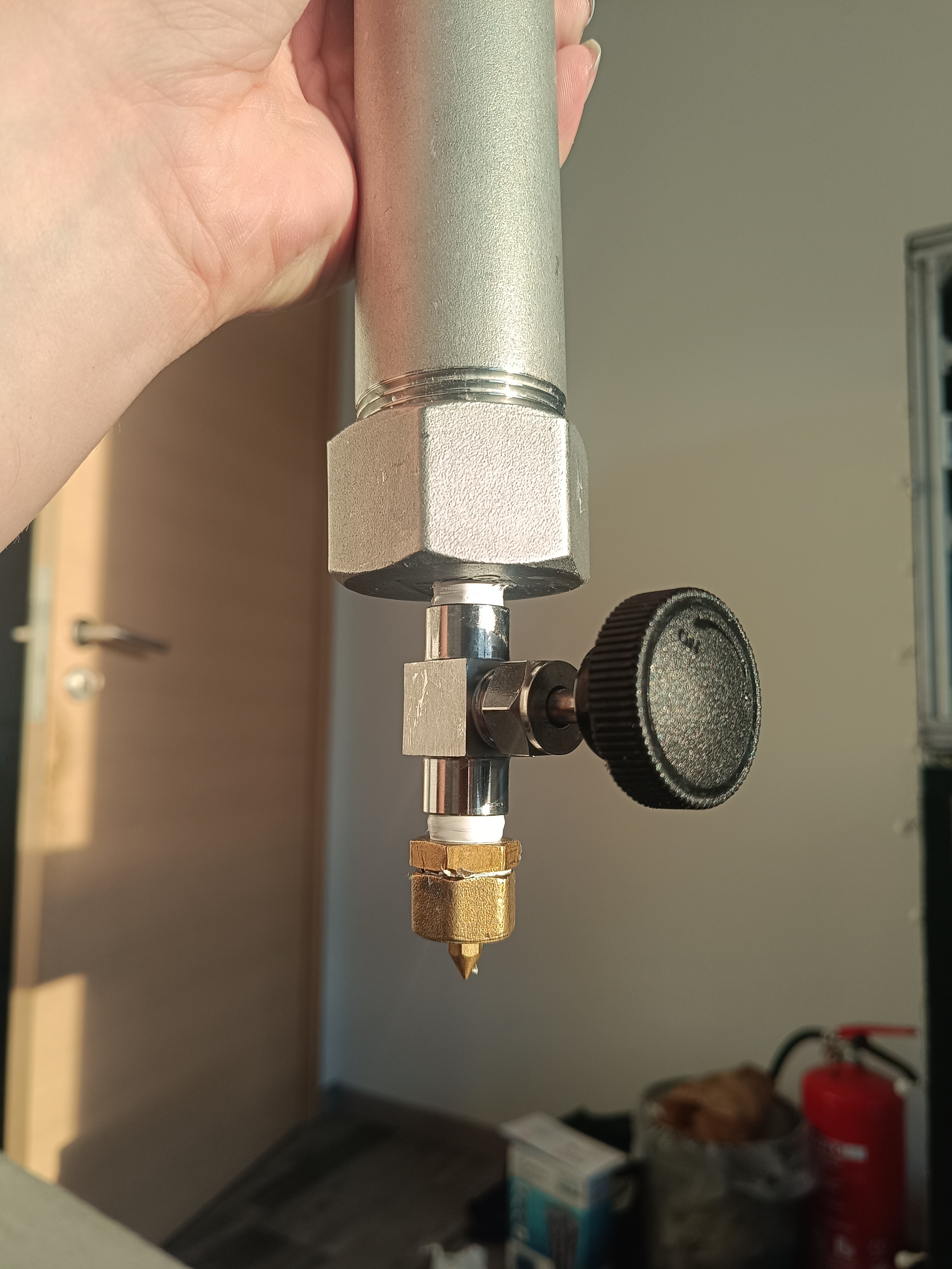
I started by building a pipe with a valve and a 1mm nozzle that I could fill with water, which I could let drop out slowly by slightly opening the valve.
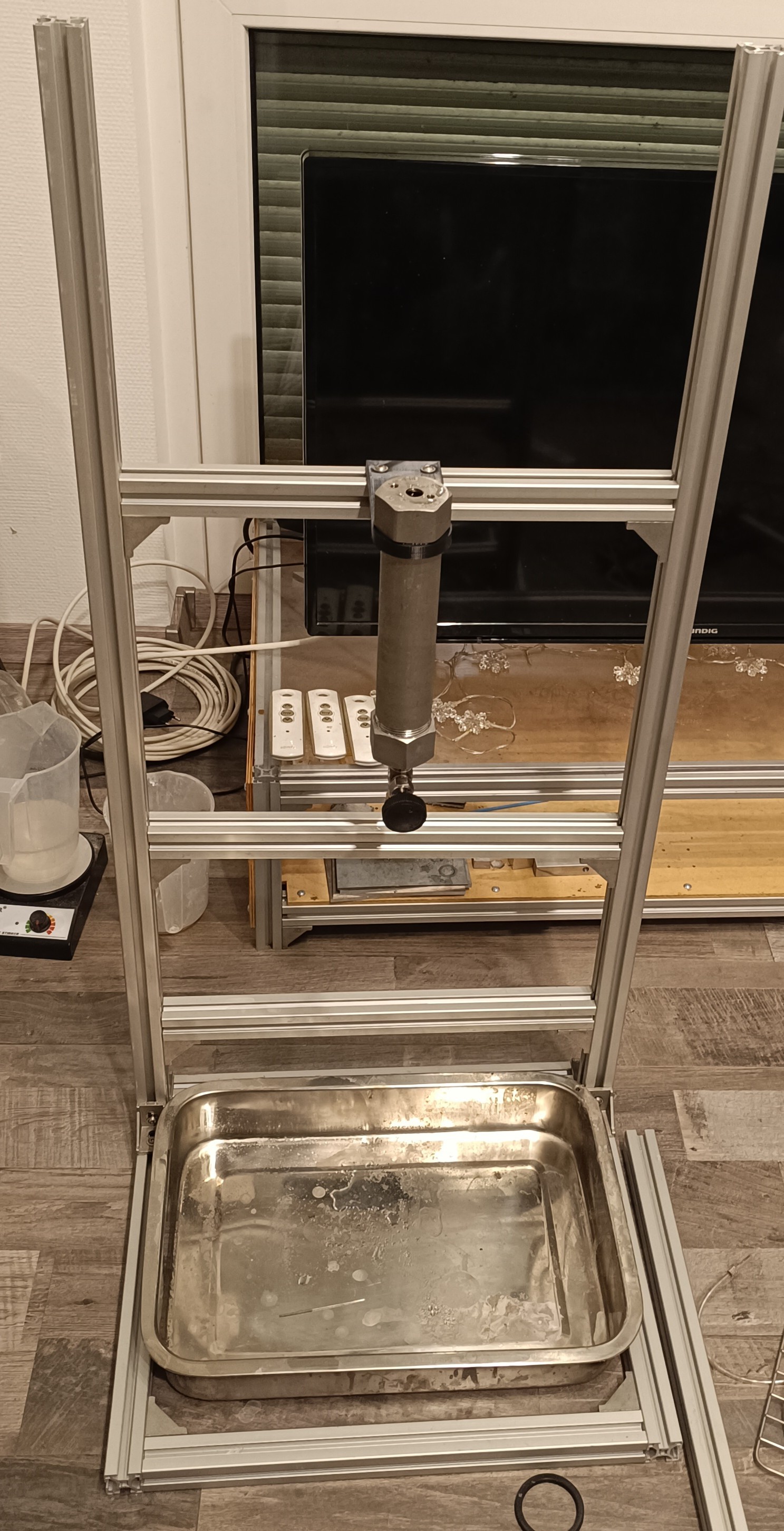
Then I built a test stand out of two 1m 3030 profiles and a few shorter pieces for attaching the pipe on it with 3D printed mounting brackets.
For charging the drops I soldered a 1.5mm² wire onto a 1/4 inch brass fitting and mounted the fitting on another 3D printed bracket.
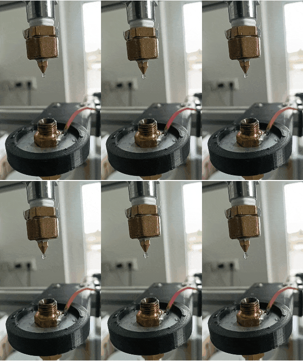
I used 56V DC for charging the drop while it passed through the fitting without touching it.
The drops get charged at the moment they break loose from the stream, so I placed the brass fitting closer to the nozzle.
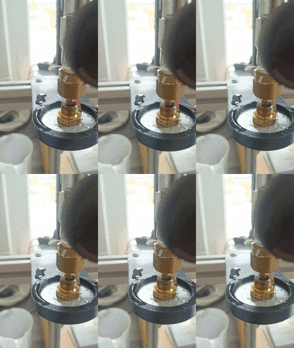
At first, I tried to sense the charge on the drop with a piece of copper mesh in a funnel connected to an oscilloscope probe which was connected to an amplifier, but because I could sense nothing but the 50Hz mains frequency with it, I tried using just the tip of the oscilloscope probe for sensing the drop.
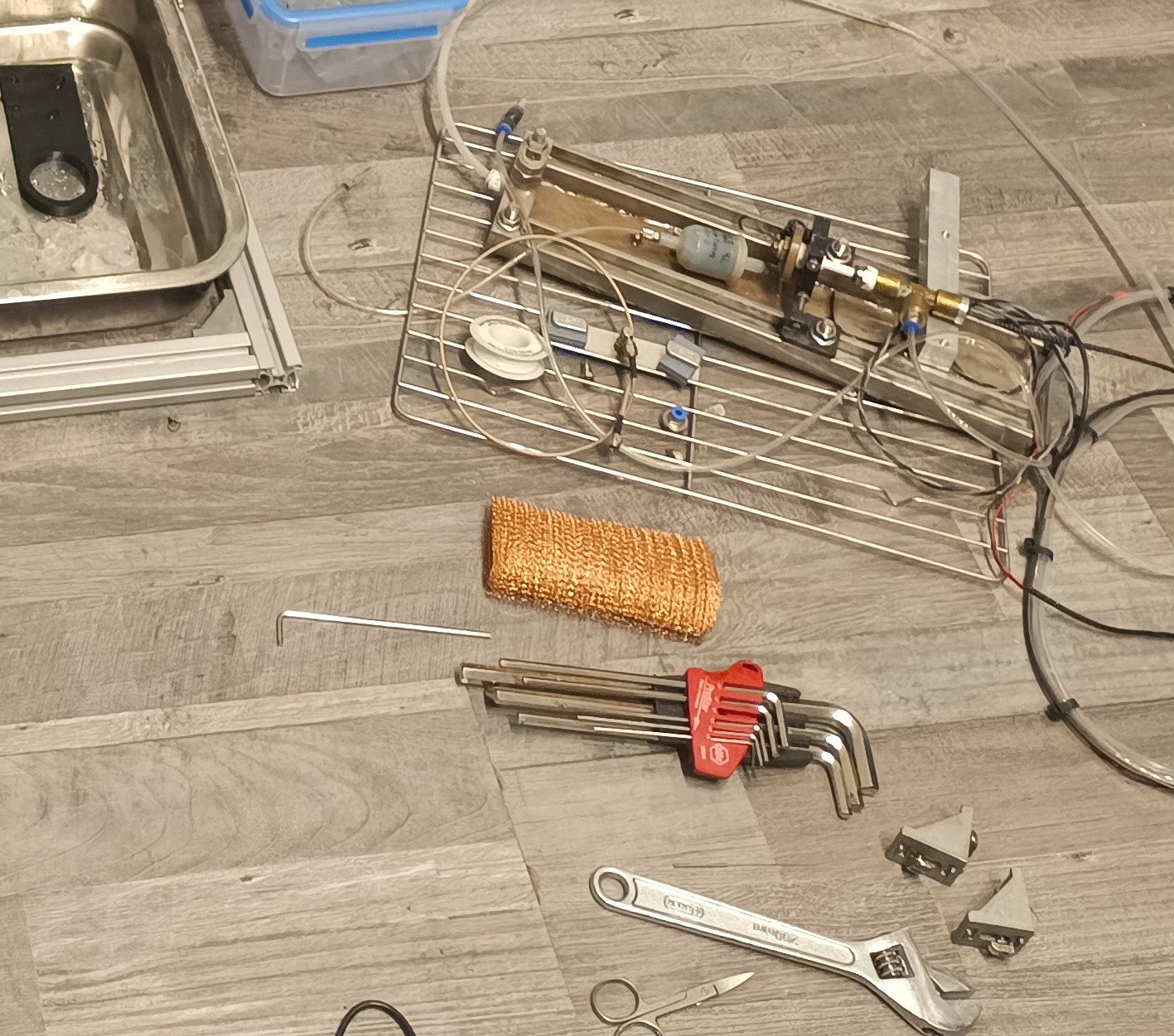
I guess the mesh acted as an antenna and picked up noise from the environment.
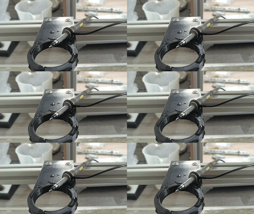
With the probe connected to the amplifier and oscilloscope, it was possible to sense the charged drops when they hit the probe's tip.
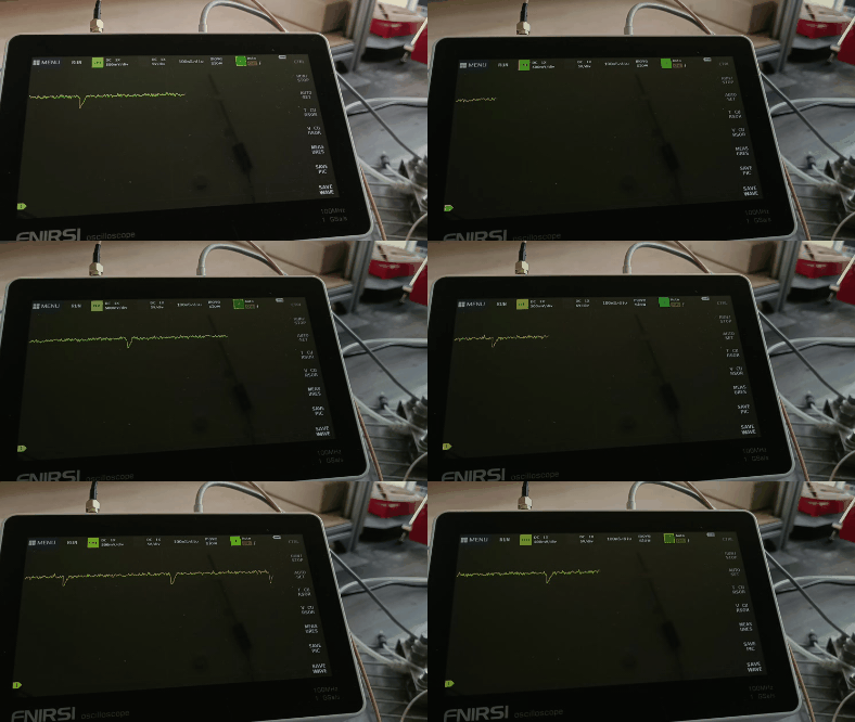
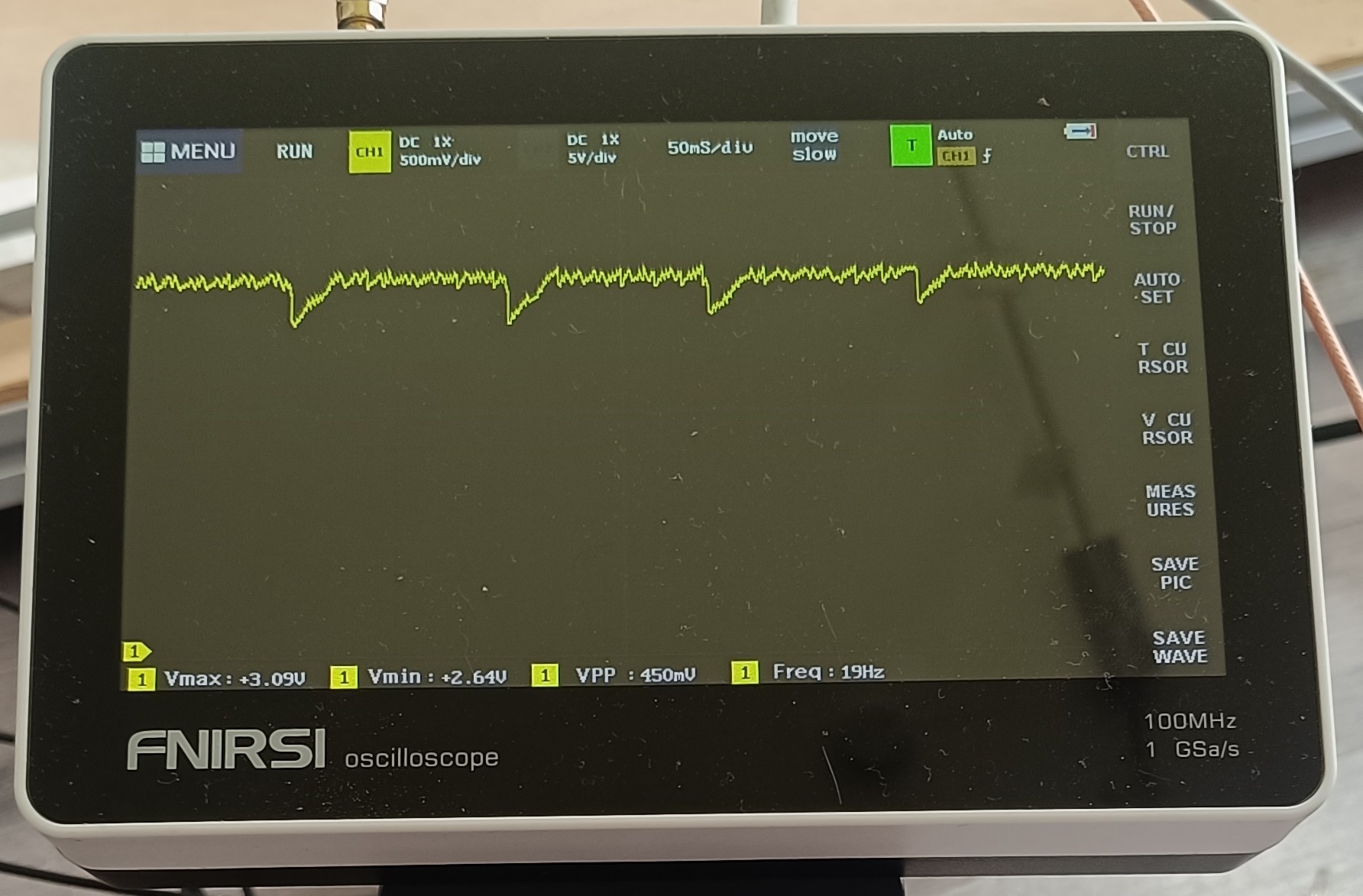
It was also possible to sense the frequency at which the drops hit the probe.
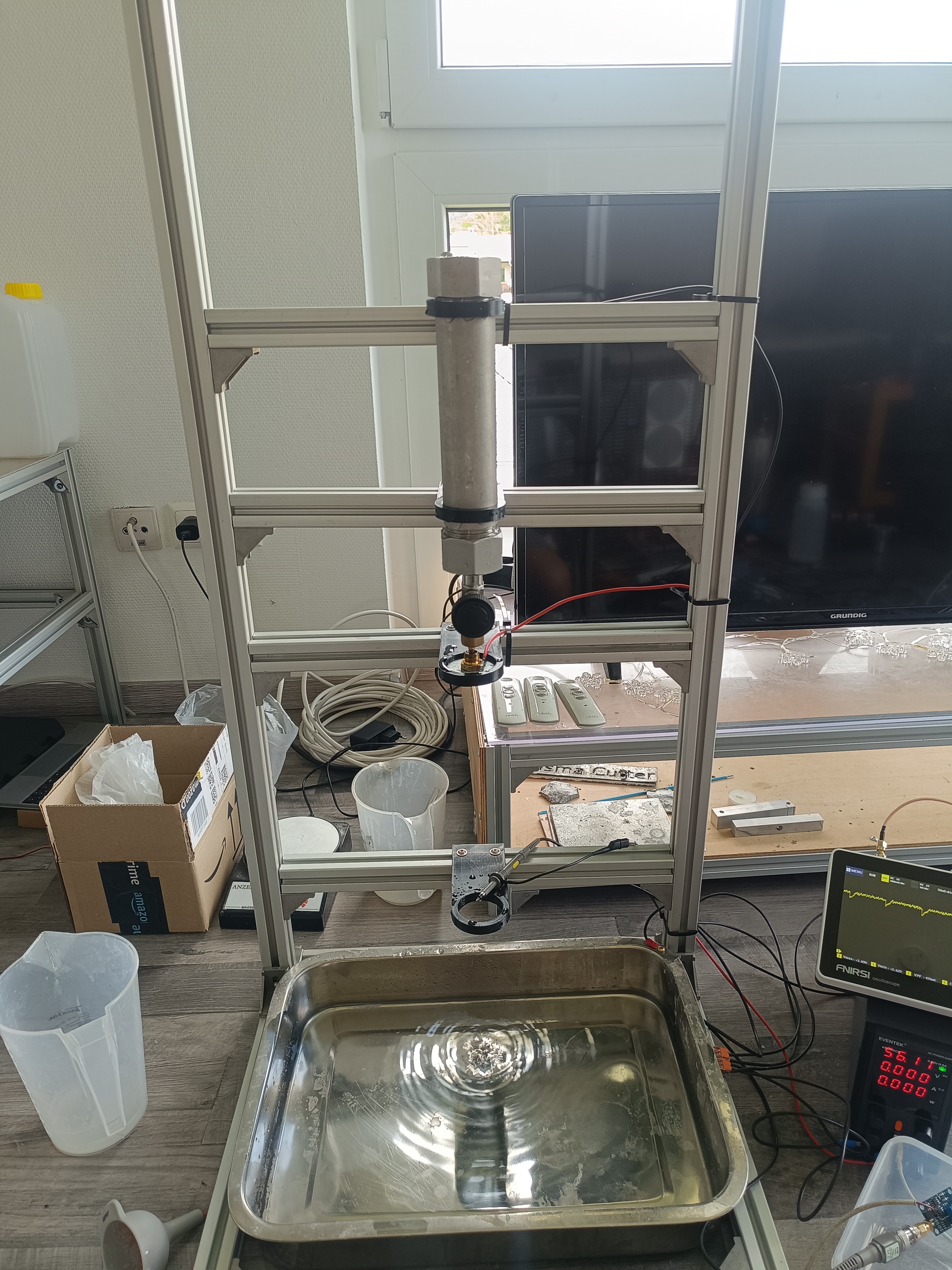
Here is a picture of the setup.
I used the AD620 instrumental amplifier module for testing. It was needed to connect the S- input to GND to get a reading out of it.
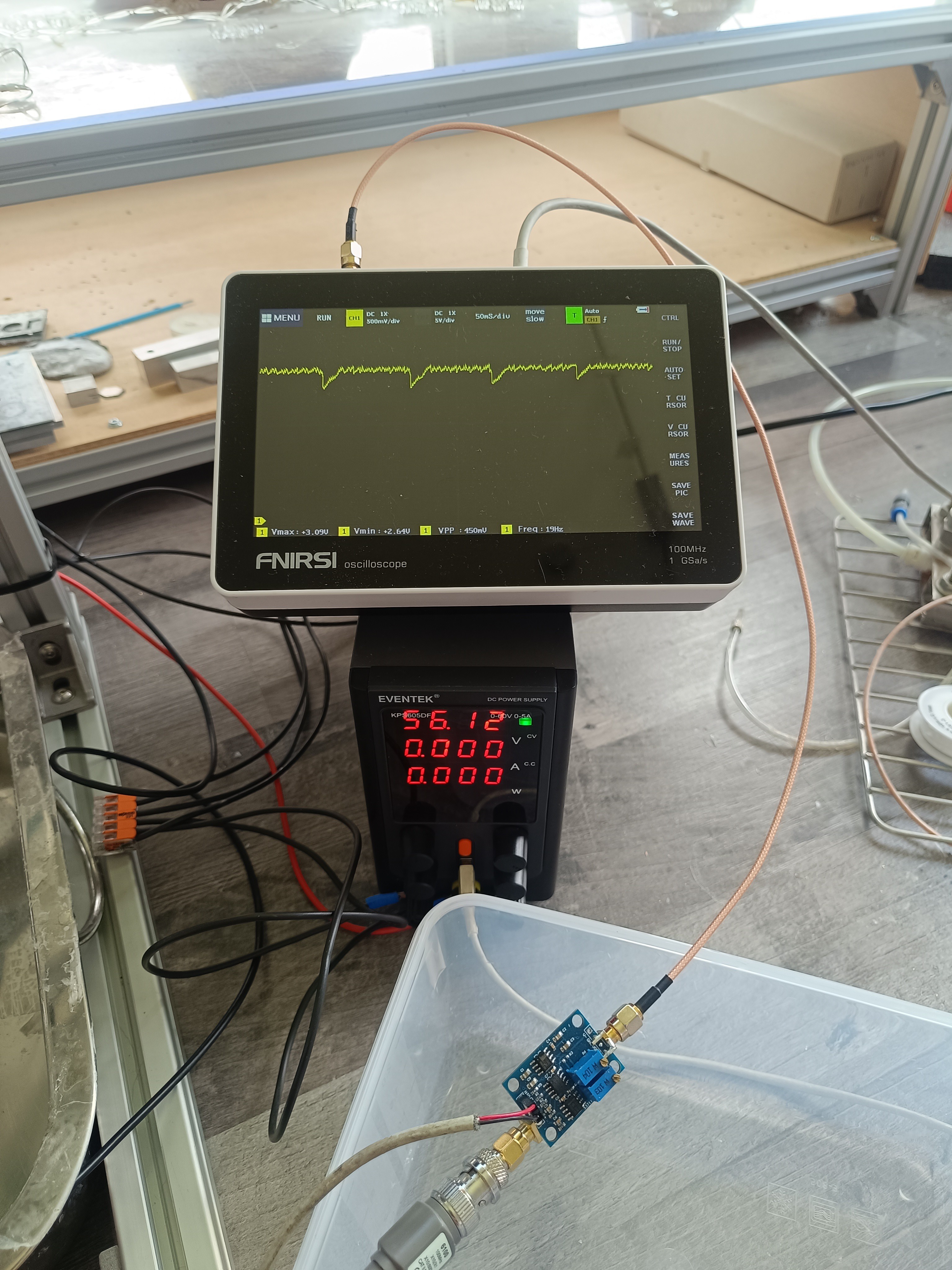
The power supply's ground was connected to the ground clip of the oscilloscope probe, the 1 1/4 pipe, the drip tray, and the frame of the stand.
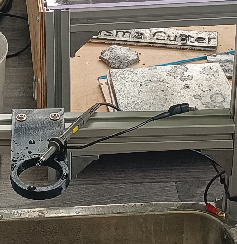
Based on the test result, it seemed like it would work to sense charged water drops with it, and to prove that it wasn't just luck, I tested 5 of the same amplifiers in the same configuration.
I also tried turning the power supply off and reducing the charging voltage, which was visible on the oscilloscope. Without a voltage, there was nothing sensed when the drop hit the probe, and a lower charging voltage resulted in a lower amplitude of the sensed signal.
When the tip of the probe was connected to the ground of the probe by water, there was also no reading visible on the oscilloscope.
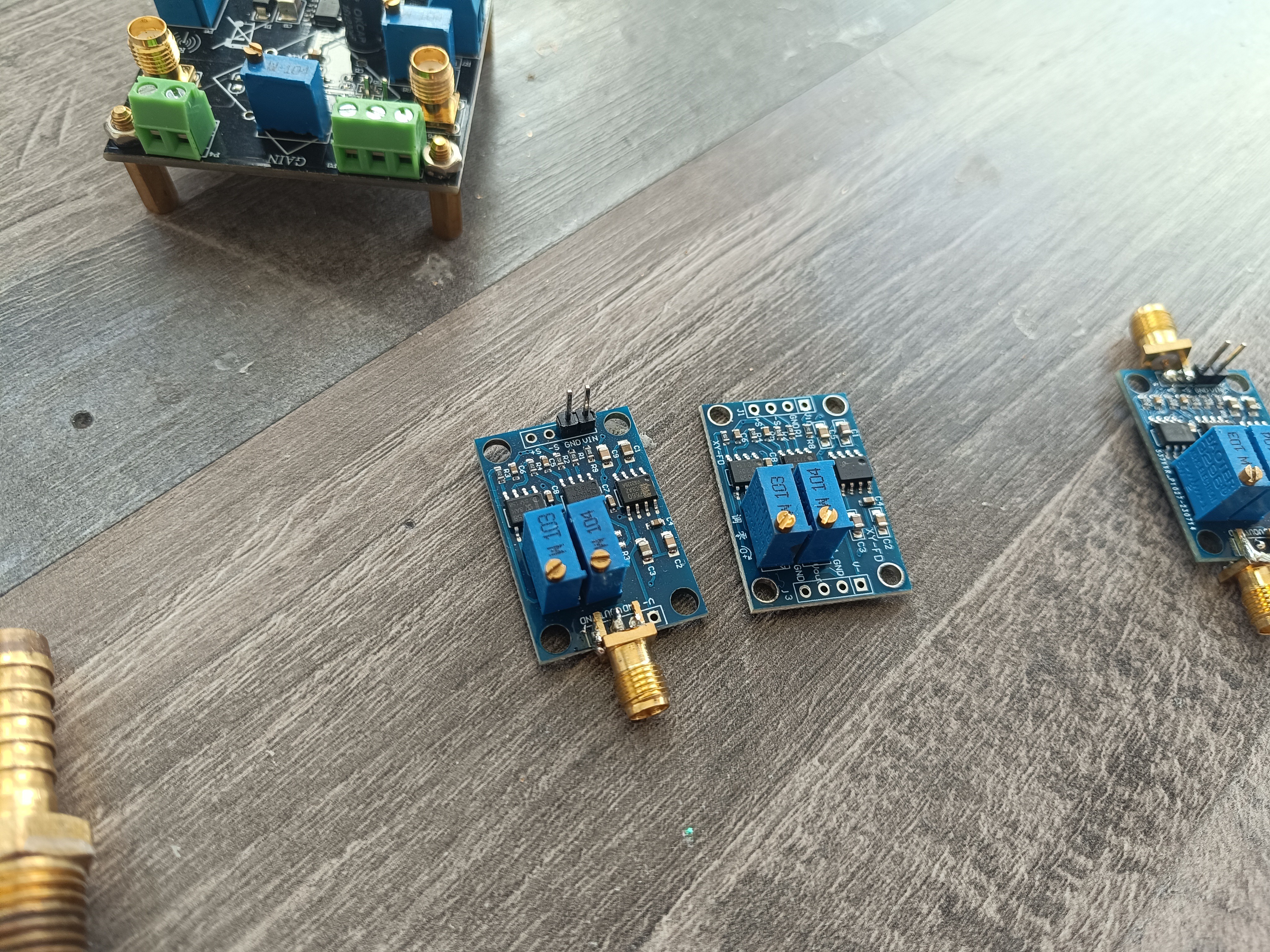
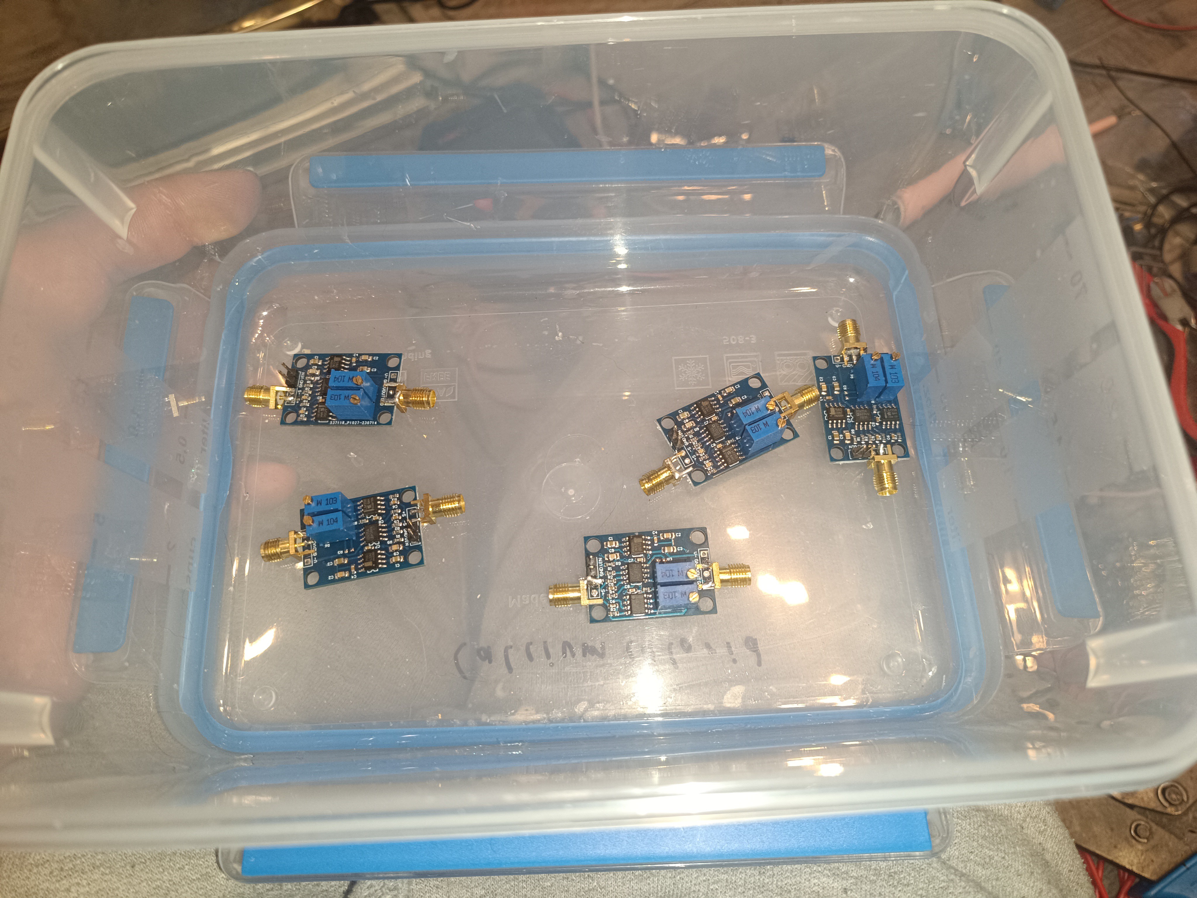
A picture of the whole setup
After finding out that it was possible to sense charged water drops, I wanted to try building a proper sense electrode to replace the oscilloscope probe.
What I want to build here is the gutter sensor of a CIJ Printer.
Many CIJ Printers have such a sensor, and while some models also have a senseless phase detection sensor (sometimes in addition to the gutter sensor), I want to focus on the type of sensor that is located in the gutter for now.
On the printhead of an older CIJ printer model, the gutter sensor looks like this from the top:
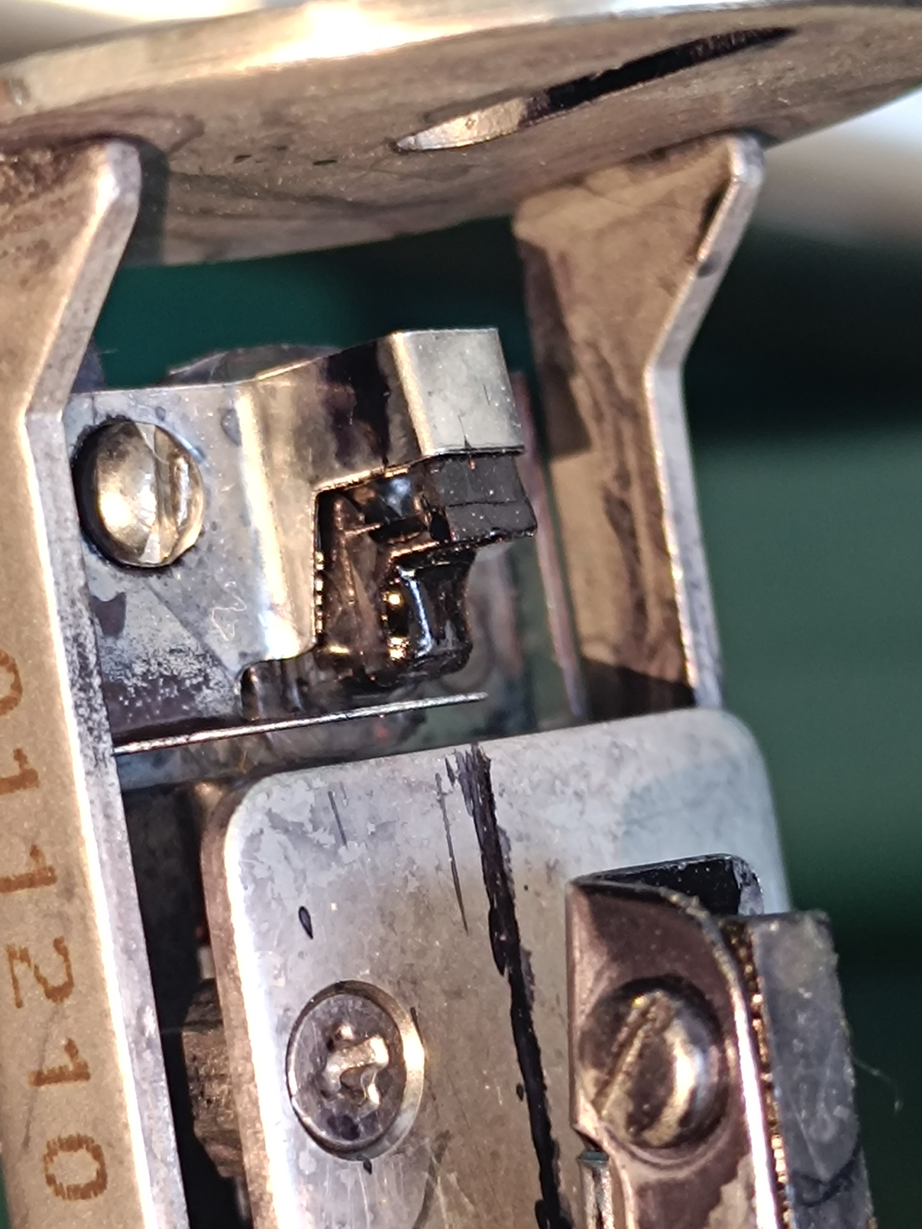
The metal on the upper part is connected to the printhead ground and covers the plastic block from the top and sides.
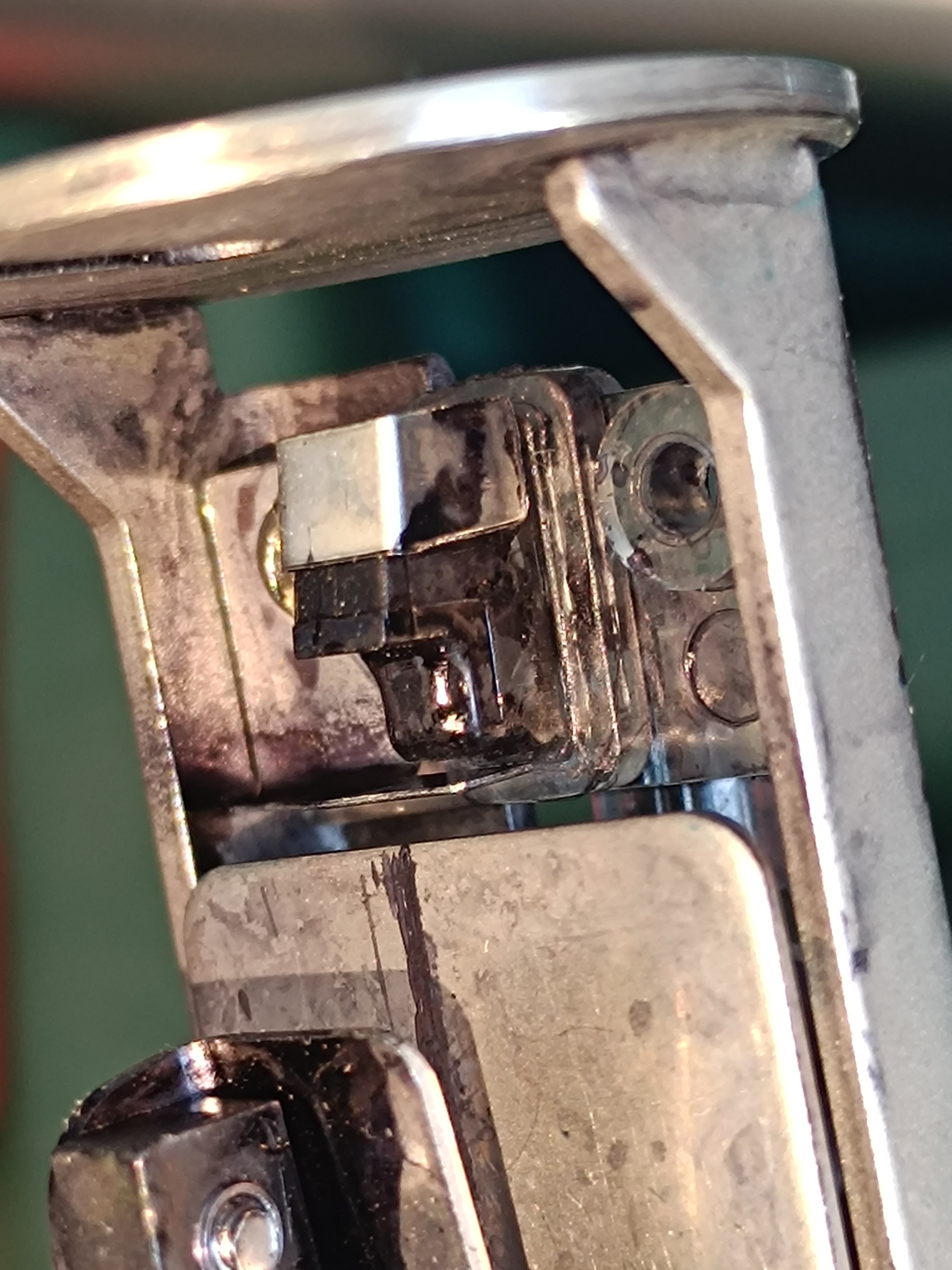
From the bottom, it looks like this:
A small metal pipe with a wire connected is attached to the plastic block.
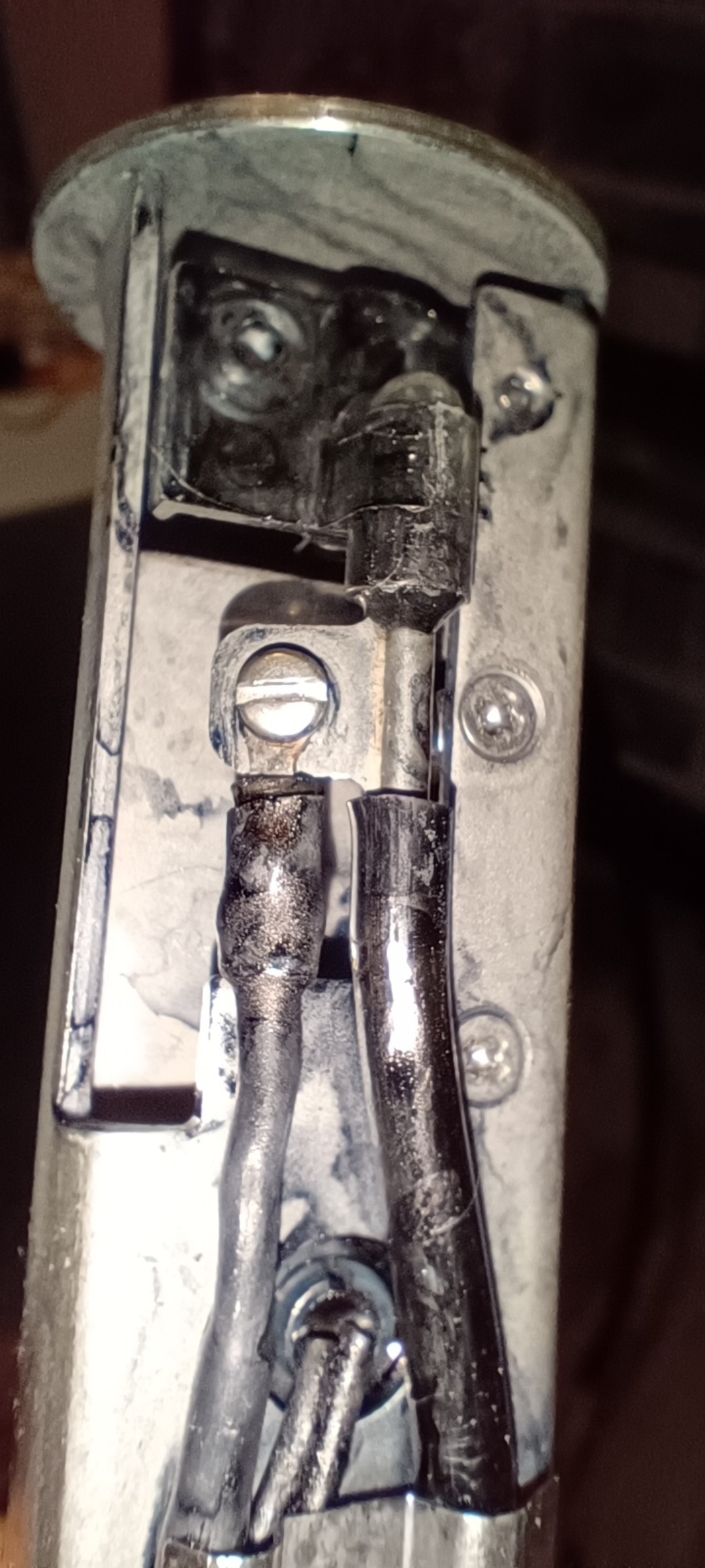
Further down the tube, there is a small metal pipe which also has a wire connected to it. Here is a picture of it with the shrink tubing removed while I was replacing the return line:
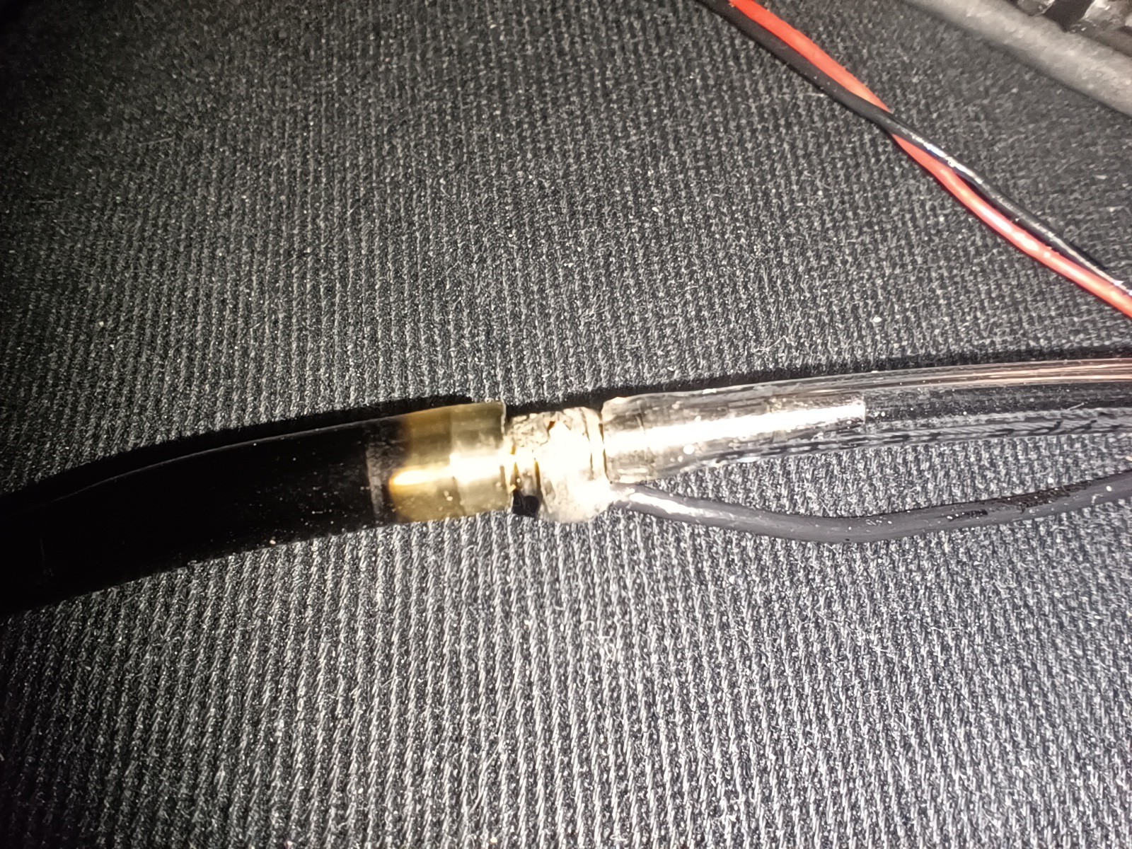
The cable that goes to the gutter sensor and about 10cm further down to the small pipe is a 3-core cable.
Here is the connection of the cable on the printer's control board:
On the left, there is the shield connection; in the middle, there is the sense connection, and on the right, there is a ground connection.
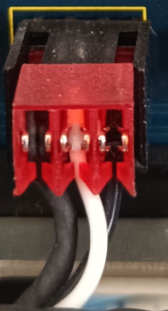
On the wiring plan, it looks like this:
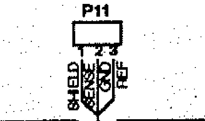
As far as I can tell, the shield is only connected to the control board and has no connection to the printhead.
The purpose of the sensor on this printer is to do two tests:
- Detecting if an ink stream is present
- Finding out which of the possible four phase shift settings that can be applied to the charge signal give the best feedback signal.
At the moment of writing this, I'm not completely sure why the ground reference is connected to the small pipe in the return line.
My guess would be that it needs a ground reference as close to the return block as possible which is not directly connected to the frame of the printhead.
Normally, there is a vacuum applied to the return line, which sucks the ink back into the printer when the ink stream hits the return block.
When I did my tests with the oscilloscope probe, I couldn't get any reading when the tip was shorted to the ground by water, but maybe the vacuum helps to prevent the buildup of a conductive path from the ground to the sensing pipe or it isn't a problem for the sense circuit used on this printer.
I will keep this in mind for building my own amplifier.
Without further ado, I tried building something by myself with the parts I had lying around:
For that, I sanded down the pins on two SMA PCB connectors and soldered them together. Then, I soldered a wire to a nut that was part of another SMA connector. After that, I screwed the two soldered-together SMA connectors into a 1/4-inch plastic fitting and screwed the nut onto the SMA connector's thread, which I secured with a screw locking ring. Finally, I pushed the plastic insulation of the SMA connector out with a screwdriver so that it could be used as a conductive tube and connected a silicone tube to its end.
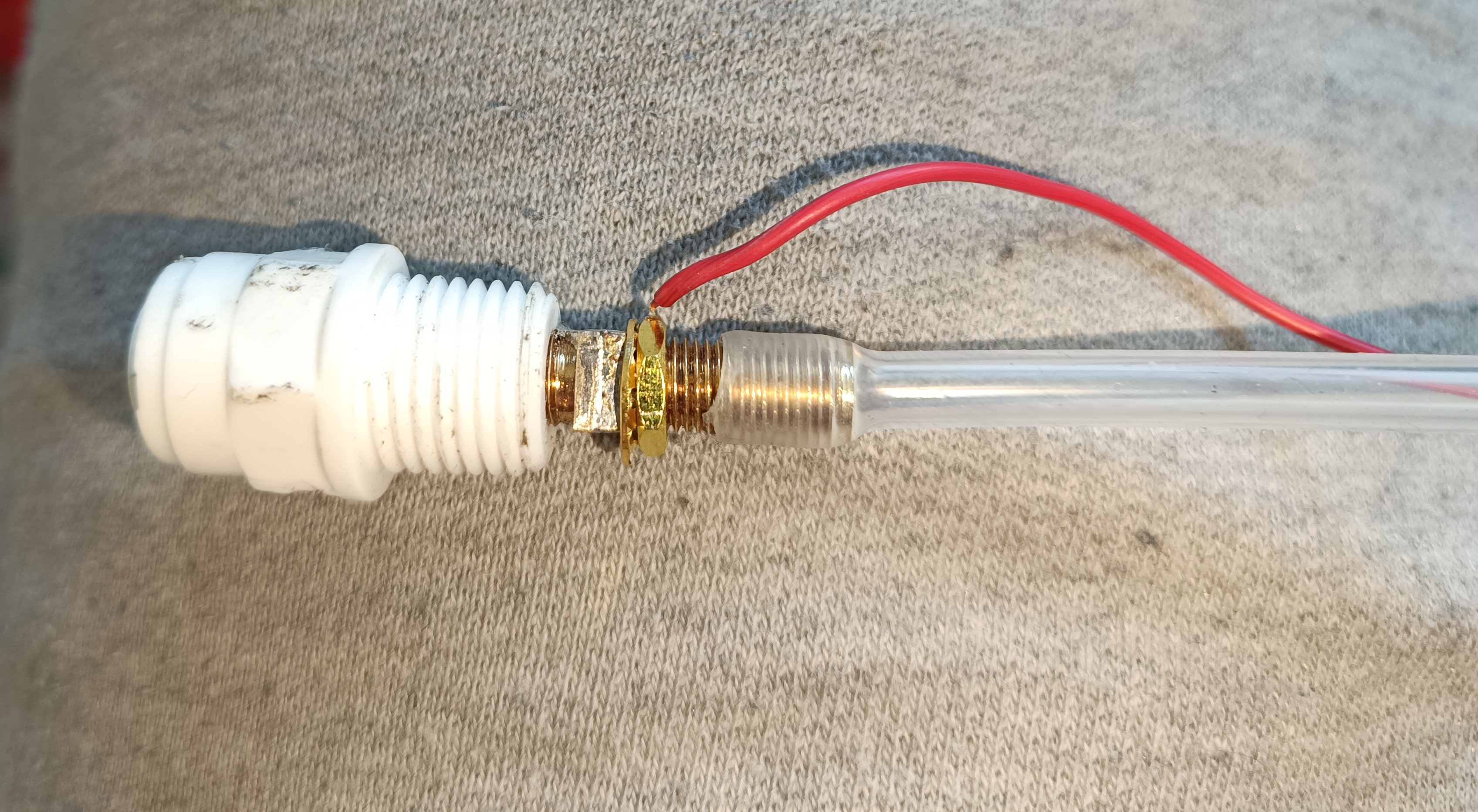
To shield it from noise, I soldered a wire to a 1/4 brass fitting which I screwed on the plastic fitting with a washer in between to attach it to the 3D printed part.
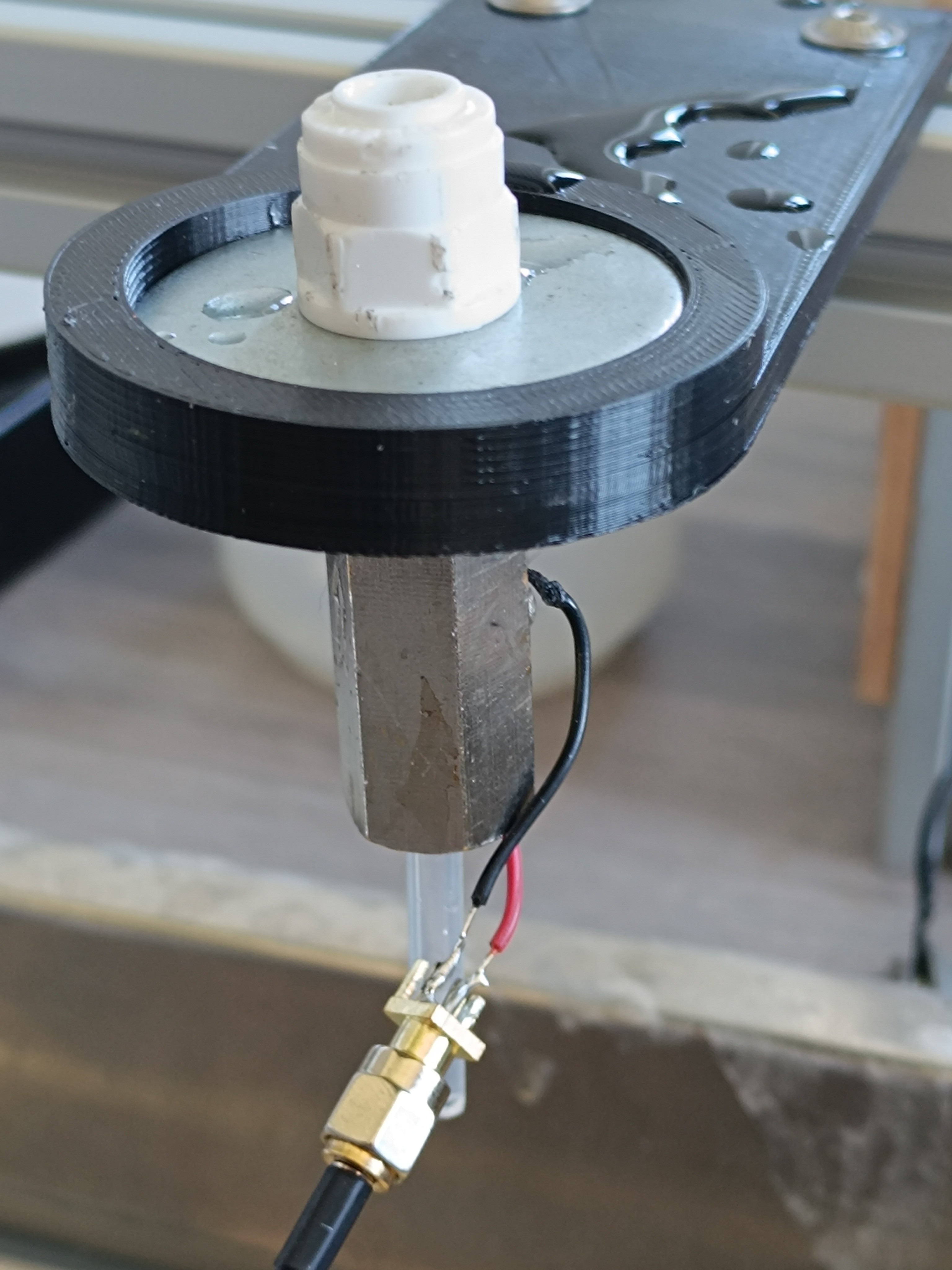
While this definitely isn't the best design, it still worked.
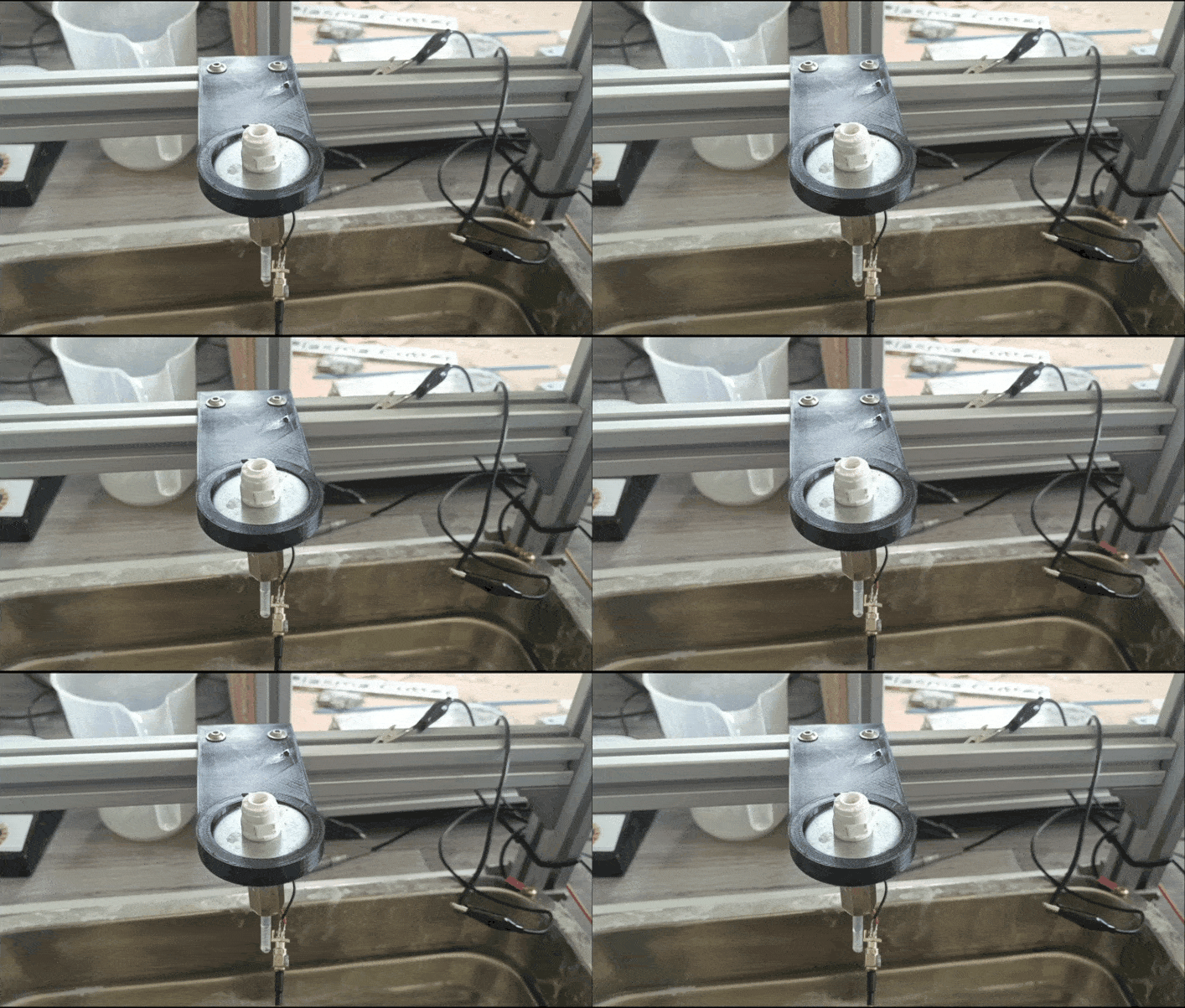
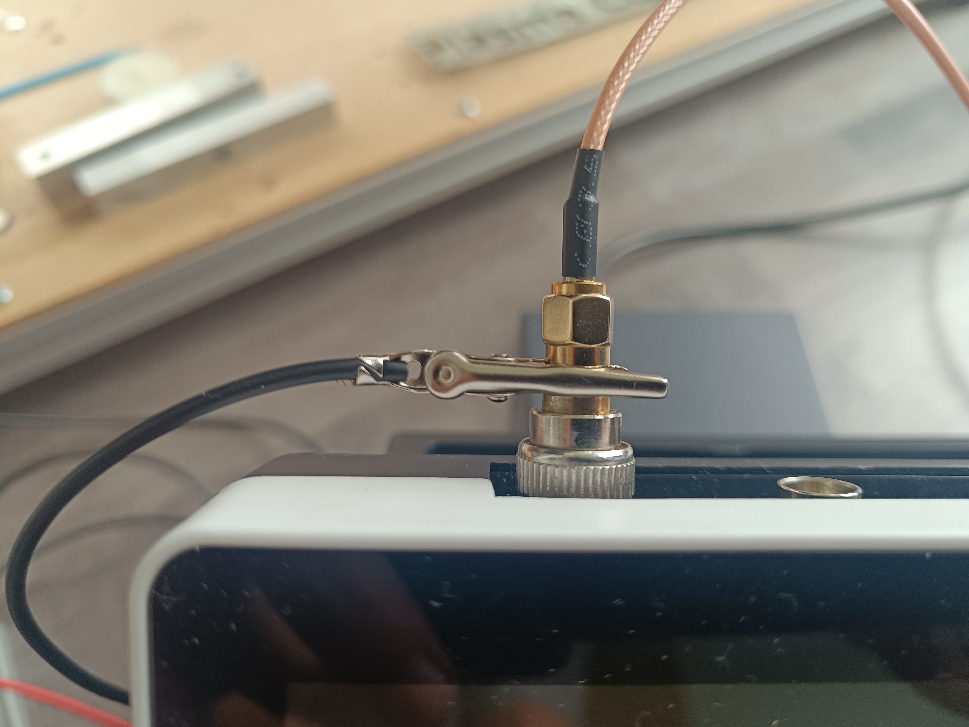
To get a reading out of it, it was important to connect the oscilloscope to the power supply's ground.
While in theory the SMA connectors which I soldered onto the AD620 amplifier module should connect the oscilloscope to the ground of the module, in reality that wasn't the case, so I had to connect it separately.
Maybe it had something to do with the bridge between S- and ground on the input side.
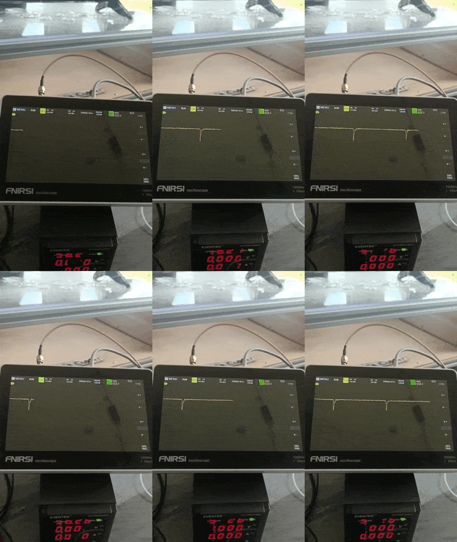
And with that, the first charging test was completed sucessfully.
Conclusion:
- It is possible to charge water drops and read when charged drops hit the sensor.
- Shielding seems to be important to not read noise like the mains frequency or noise from power supplies.
- An amplifier is needed to amplify the small voltage from the drop's charge so that it can be read.
- There is more research needed regarding the ground connection of the amplifiers.
- It would be the best to build a custom amplifier for amplifying the charge to learn more about this topic.
- In the future, a better DIY gutter sensor design is needed.
I think it's useful to do such experiments to verify that something works by yourself instead of only relying on informations you have read online. This way you also get something you can base your next experiments on.
 Dominik Meffert
Discussions
Become a Hackaday.io Member
Create an account to leave a comment. Already have an account? Log In.