 Dominik Meffert
Relation between Jet Velocity and Pressure, Viscosity
In CIJ printing, there are two important key values that can change during operation, so it's important to track and control them.
These are viscosity and pressure which both affect the jet velocity:
- An increase in viscosity leads to a decrease in jet velocity while a decrease in viscosity leads to an increase in jet velocity when the pressure stays constant.
- An increase in pressure leads to an increase in jet velocity while a decrease in pressure leads to a decrease in jet velocity when the viscosity stays constant.
Viscosity is affected by temperature changes and solvent evaporation. A higher temperature leads to a lower viscosity and a lower temperature leads to a higher viscosity. A higher solvent content leads to a lower viscosity and a lower solvent content leads to a higher viscosity.
Relative Viscosity is measured by a falling ball viscosimeter and the ink temperature can be controlled by a Peltier module. The solvent content can be controlled by adding solvent via a peristaltic pump or by adding pre-mixed ink to the ink tank. Adjusting the temperature and solvent content usually takes some time until the solvent has mixed with the ink and the set temperature is reached.
In contrast to that, pressure is not affected by external factors and can be measured with a pressure sensor and controlled with a pressure regulator or a PWM-controlled pump, which makes fast and precise pressure adjustments possible.
Since a constant jet velocity is important for reliable operation and good print quality I added a way for measuring the jet velocity to the printer.
Great thanks to Robert H. and @Paulo Campos for helping me with that.
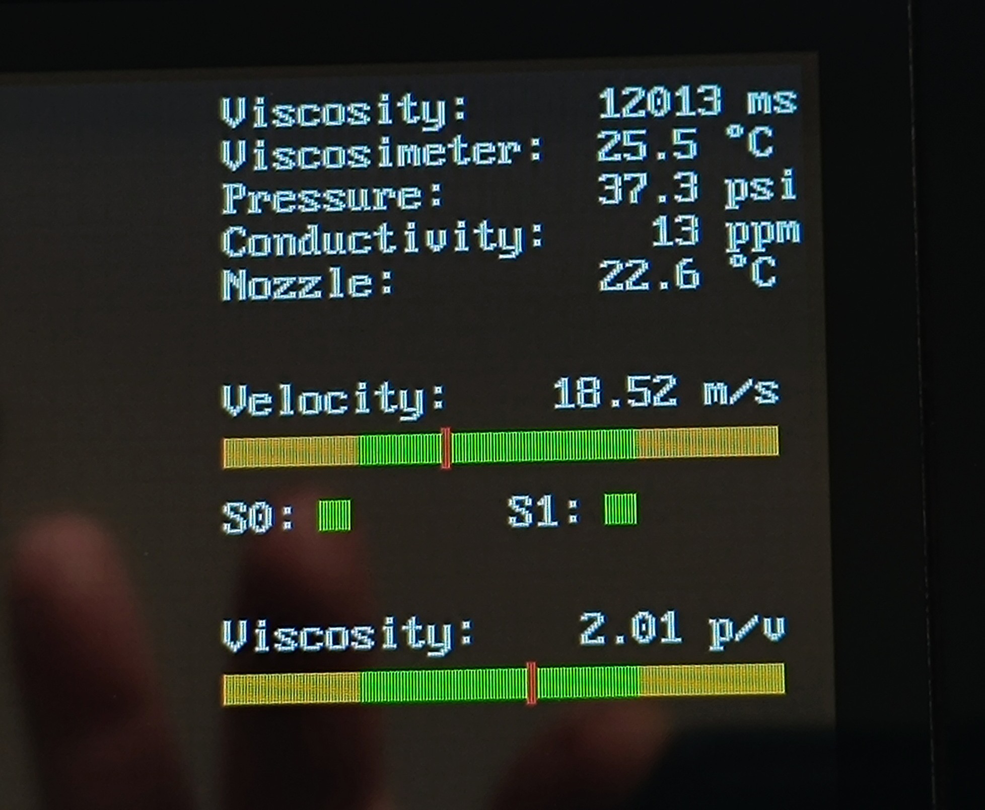
The jet velocity is measured by counting the Time of Flight (TOF) that an ink droplet needs to travel between two sensors that have a fixed distance between each other. The distance is then divided by the TOF to get a reading in distance per time.
This new TOF sensor should make it easy to keep the jet velocity constant by looking at the reading while adjusting the pressure. Currently, I'm using a bar with a "proven to be good" value in the middle and a small good range around it while adjusting the pressure regulator by hand. In the future, this could be automated if needed.
S0 and S1 are timeout indicators that can help with troubleshooting by indicating which sensor has a problem.
I also added another reading which shows the ratio between pressure and jet velocity to get information about how much changes in viscosity affect the jet viscosity.
Recent tests have shown that with the viscosity of the currently used resin ethanol mix, small changes in viscosity caused by temperature variation have very little effect on the jet velocity. Since the printer is used inside the house the ink temperature should also not drop much below 20⁰C and rise not much above 30⁰C.
Based on this, I think changes in room temperature across different seasons will have less effect on the viscosity and jet velocity than solvent evaporation over time.
In contrast to that, each psi difference has a noticeable effect on the jet velocity, so that a more precise pressure control would have a positive effect on reliability and print quality.
TOF Sensor as Functionality Test
In addition to measuring the jet velocity, the TOF sensor can also verify the function of breakup and charging. It relies on charged groups of ink droplets for time measurement, which is only possible if both processes are working correctly.
When no signal is detected on the TOF sensor this can indicate the following problems:
- A clogged nozzle
- A misaligned jet
- Problems with the piezo
- Problems with the charge electrode
- Problems with the TOF sensor
This can help with troubleshooting and could be used for pausing the print in the future if a problem is detected.
Building the TOF Sensor
The TOF sensor is based on all the previous progress on the printer project since it is the first component that actually relies on the full breakup and charging process which makes it an important milestone in the project.
The TOF sensor is made out of the actual sensor and the electronics for processing the signal.
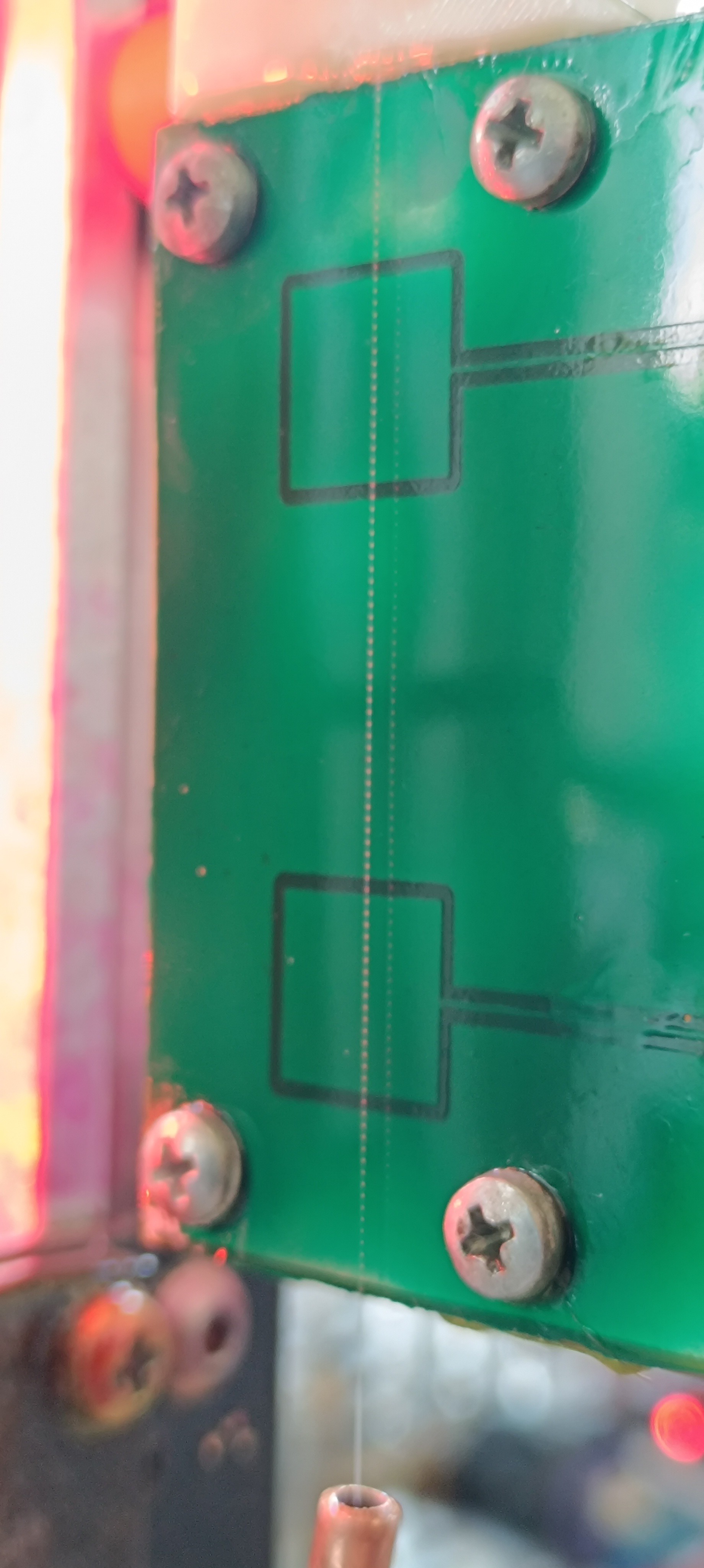
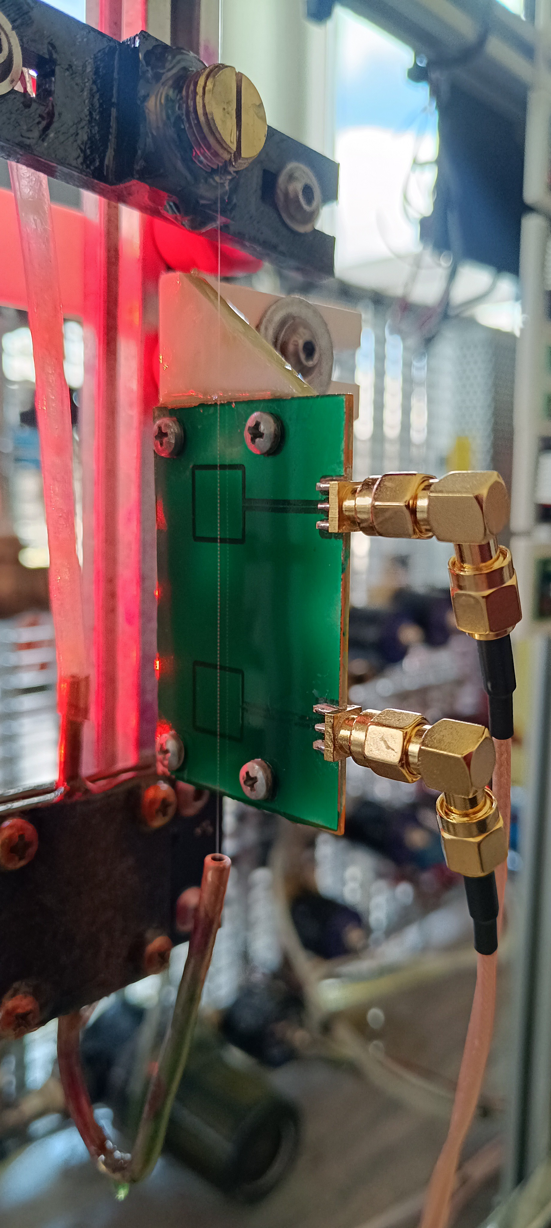
The currently used sensor is made out of a PCB which includes two sensor surfaces surrounded by a grounded area. Each sensor is connected to an SMA connector, which leads to an amplifier.
The current design may be a bit large, and its size could be reduced in the future.
Using a PCB for the sensor already helped reduce its size and keep the distance between both sensors constant.
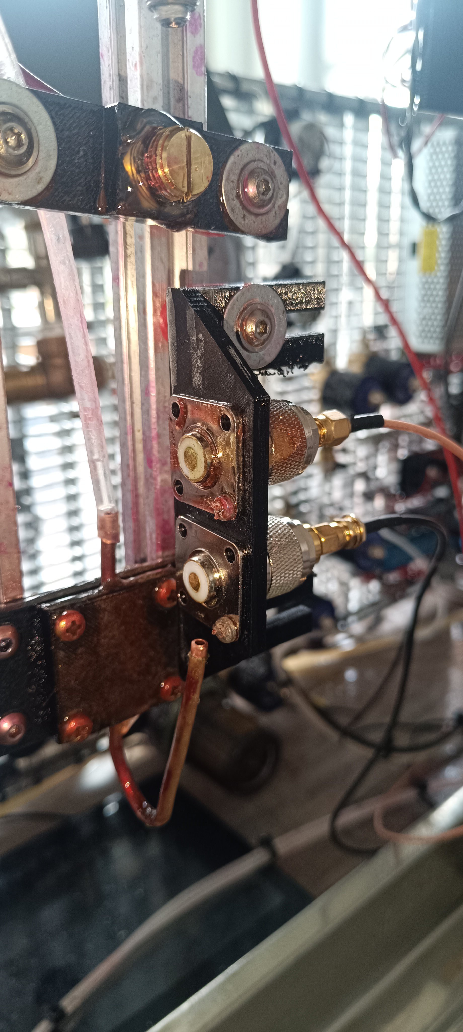
The first prototype used bulky UHF connectors, but it was already possible to measure the charged droplets with it.
Designing and building the sensor itself was the easiest part. The much harder part was building the circuit to get a usable signal out of it.
The next build log will describe this in detail.
Discussions
Become a Hackaday.io Member
Create an account to leave a comment. Already have an account? Log In.