 Dominik Meffert
For the last weeks, I was searching for a way to adjust the ink pressure via software, so that the printer can react to changes in room temperature and viscosity to keep the jet velocity constant.
Until now, I used a pressure regulator to adjust the pressure by hand while looking at the jet velocity indicator. For controlling pressure via software, it was necessary to either get a new pressure regulator that could accept a control signal or add a motor to the existing pressure regulator. Since I had problems with other pressure regulators getting stuck from dried ink in the past - the ethanol sandarac ink is very sticky and could easily be used as a medium strength glue - I preferred to stay with the pressure regulator that worked and so I started looking for a way to add a motor to it.
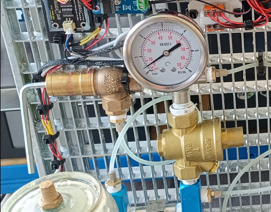
While commercial CIJ printers usually use a PWM-controlled ink pump in combination with a fixed size restriction in a feedback line, this is currently not an option for this project, since these specialized pumps are very expensive and the cost for building this printer should be as low as possible with no specialized parts. Because of that, I'm currently using a cheap ULKA EX5 24V vibratory pump in combination with a relief valve for setting the pump pressure (usually to 50 psi), a pressure regulator for setting the ink pressure (varying between 30 and 40 psi), and a damper that helps keep the pressure stable.
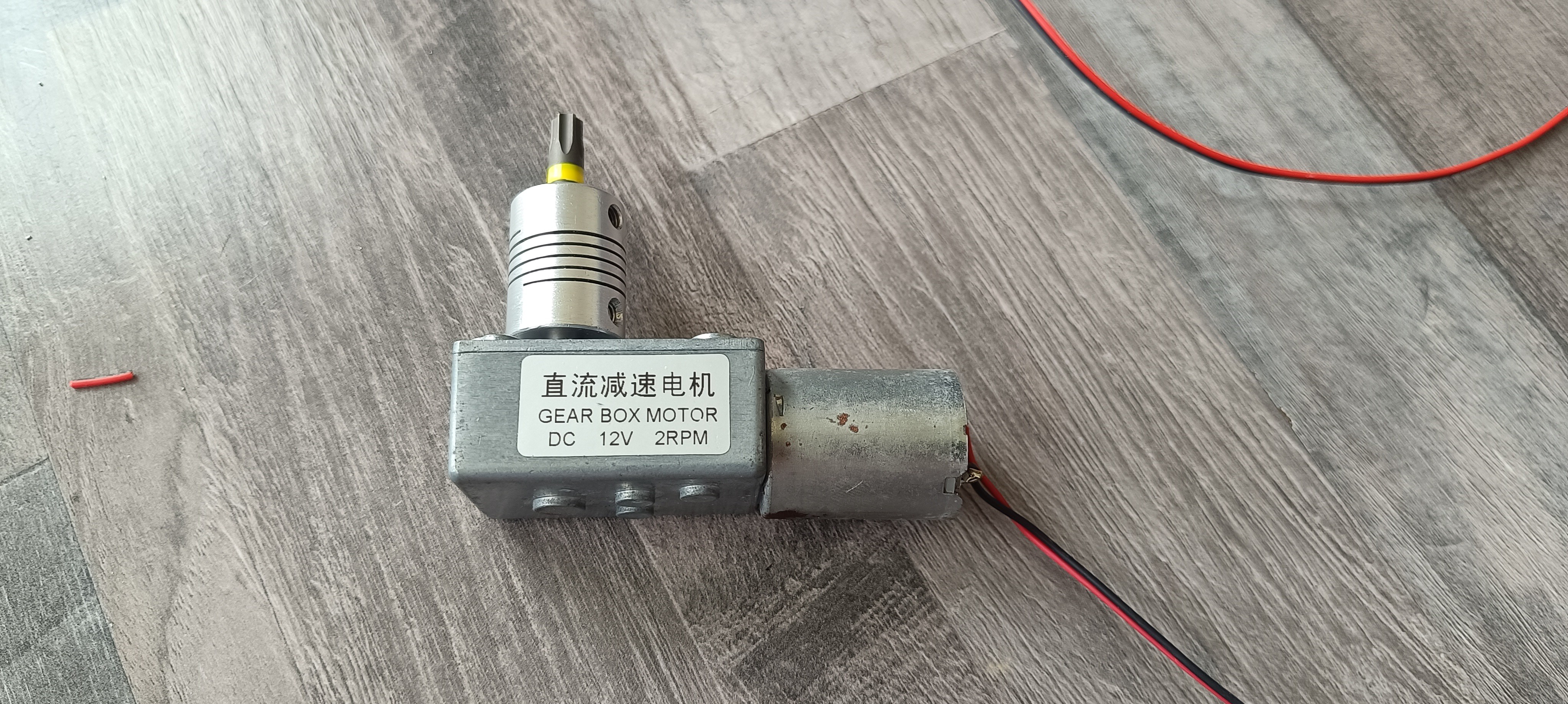
I started by testing out some geared DC motors I had at home and quickly realized that the pressure regulator model I'm using needs more torque to turn than the motors I had could provide.
Because of that, I looked for something that could provide more torque and got an old windshield wiper motor.
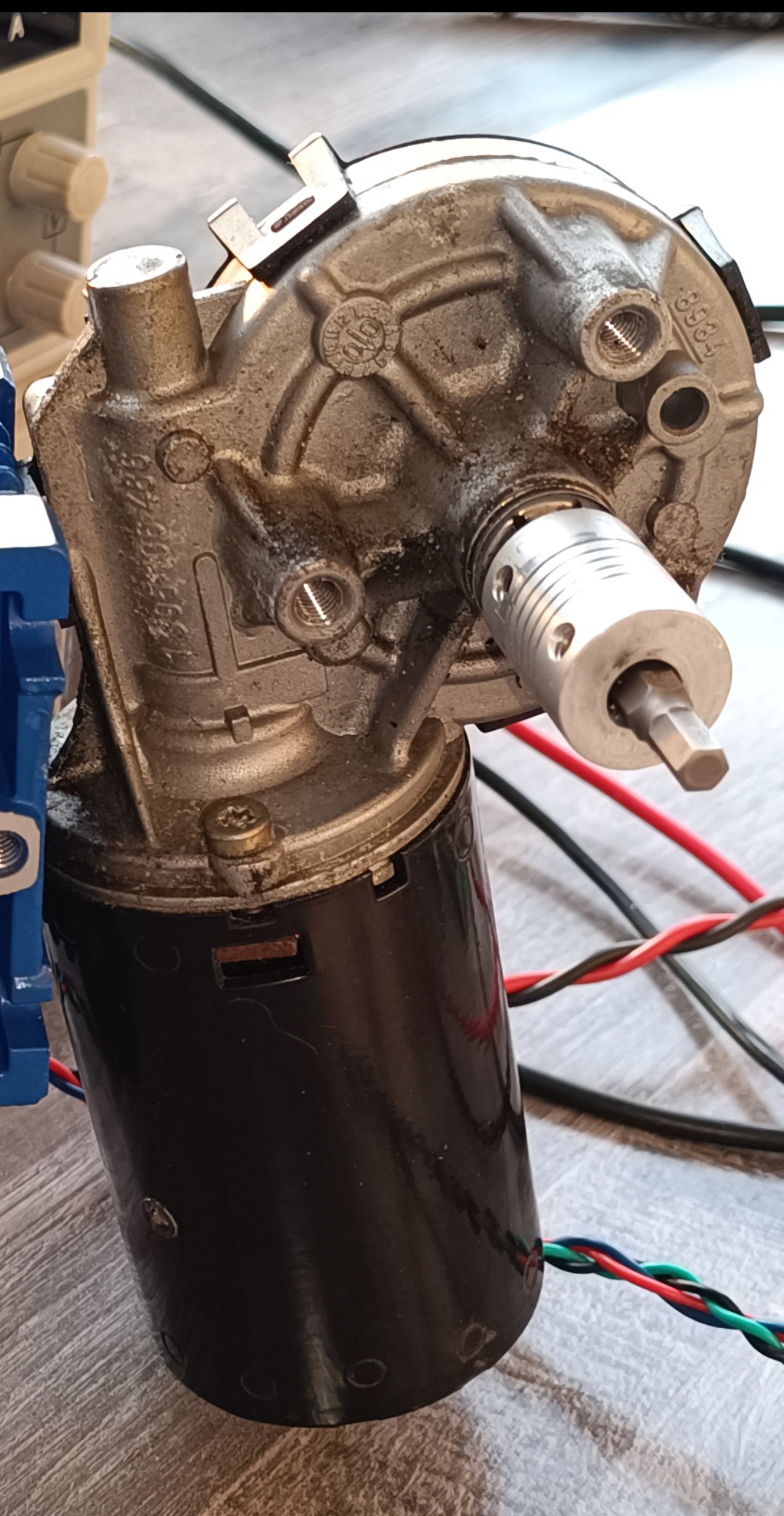
The motor had enough torque to turn the pressure regulator, and I could control direction and speed with an H Bridge. After trying the motor out for a while, it turned out that the speed of the motor could only be reduced to some extent until the motor failed to start up, and that the motor coasted for a bit when not actively braked, so that the precision was not that high with this setup. Another problem with it was that there was no way for the software to know the motor's position, so that the motor could overtighten the pressure regulation screw and damage the pressure regulator if the pressure sensor reading or TOF reading were incorrect.
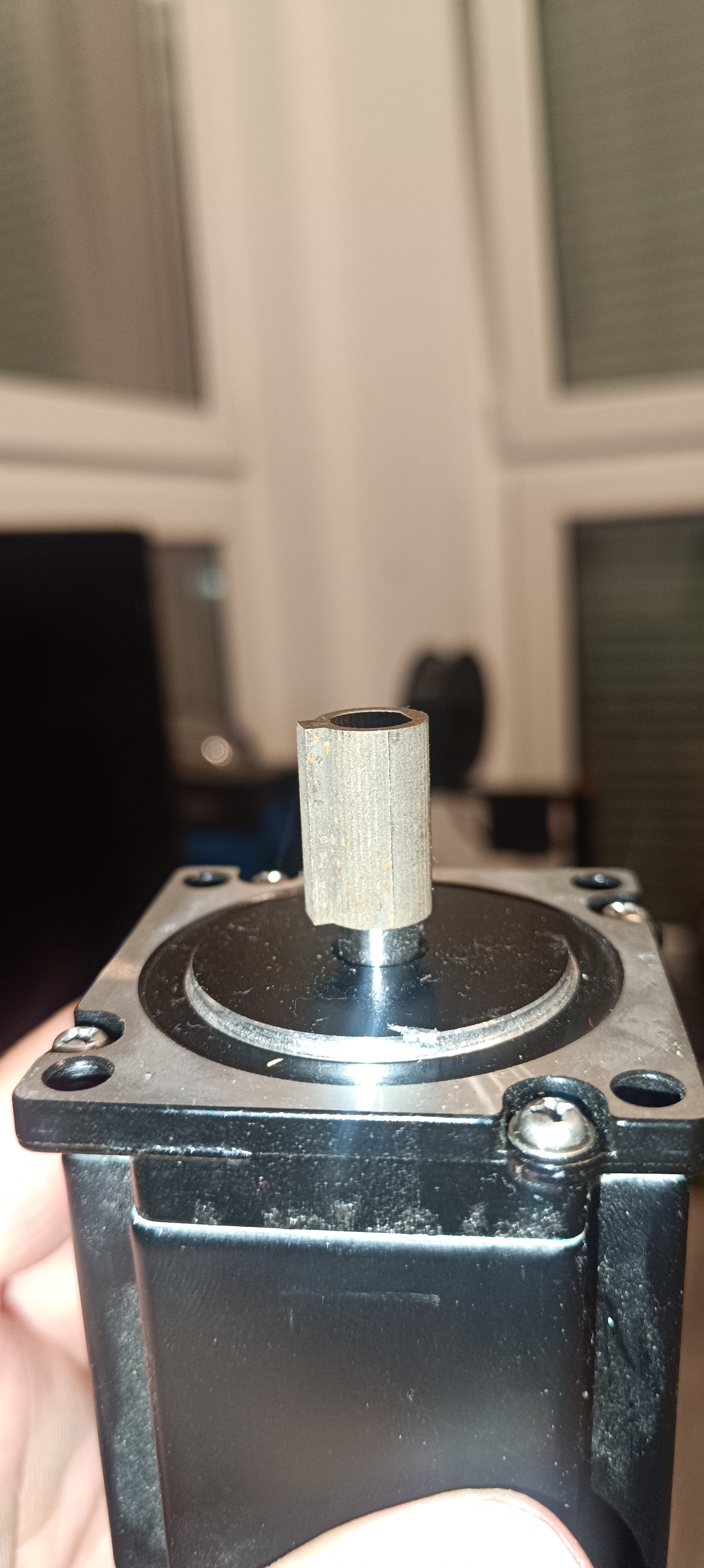
Because of these problems, I decided to use a Nema 23 stepper motor in combination with an NMRV030 50:1 gearbox and a 3590S multiturn potentiometer to get more precision and position feedback.

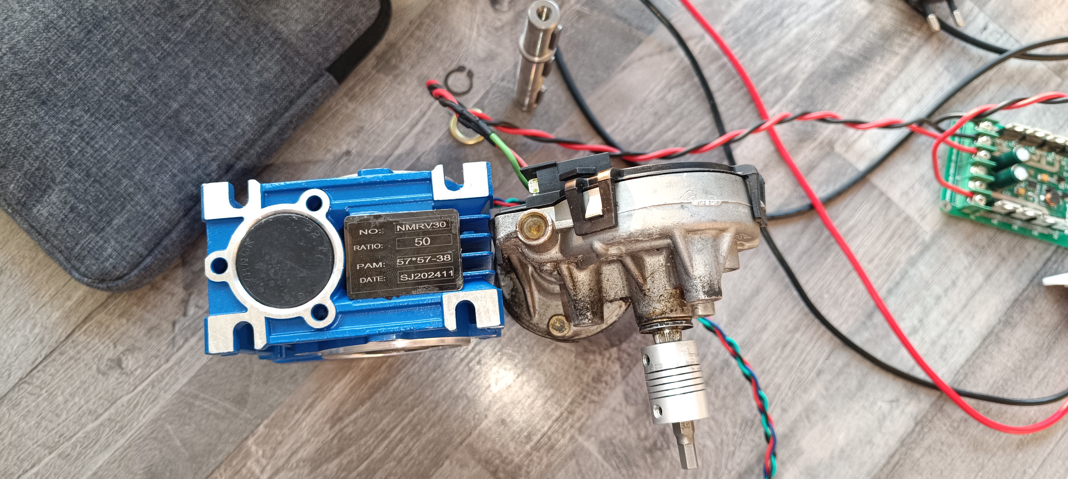

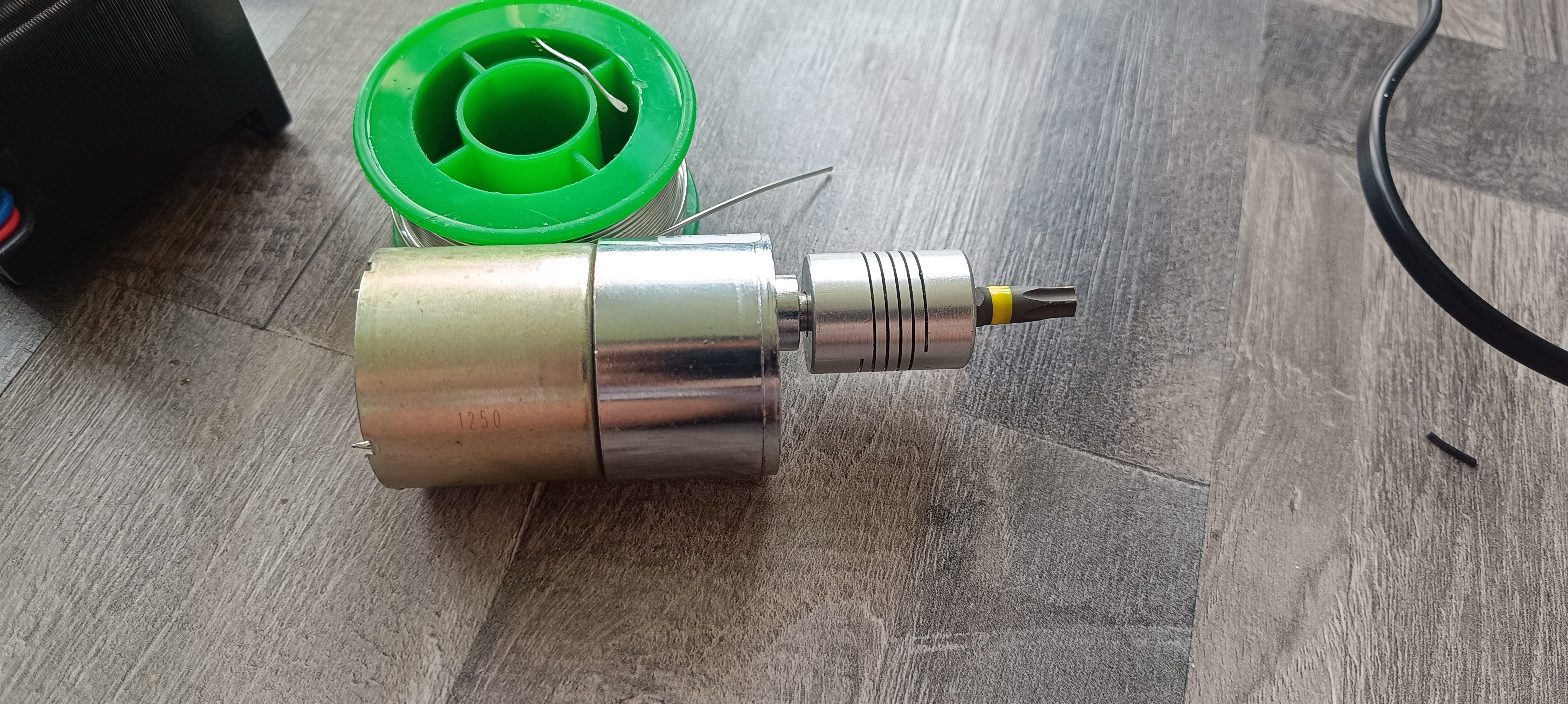
When the gearbox arrived, I 3D printed a shaft adapter and mounted the motor onto the gearbox.
With the adapter in place, the gearbox was ready for testing and designing a mounting bracket for the multiturn potentiometer.
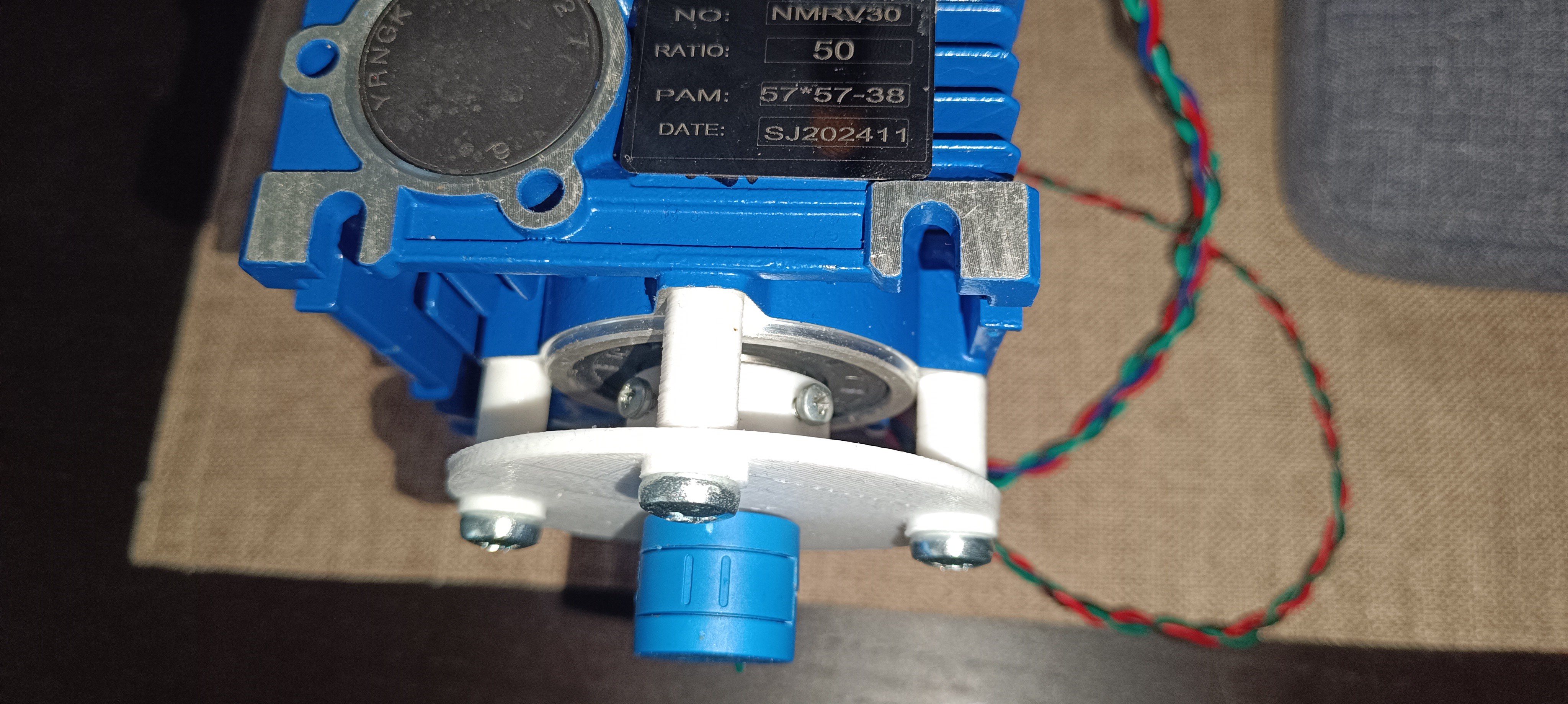
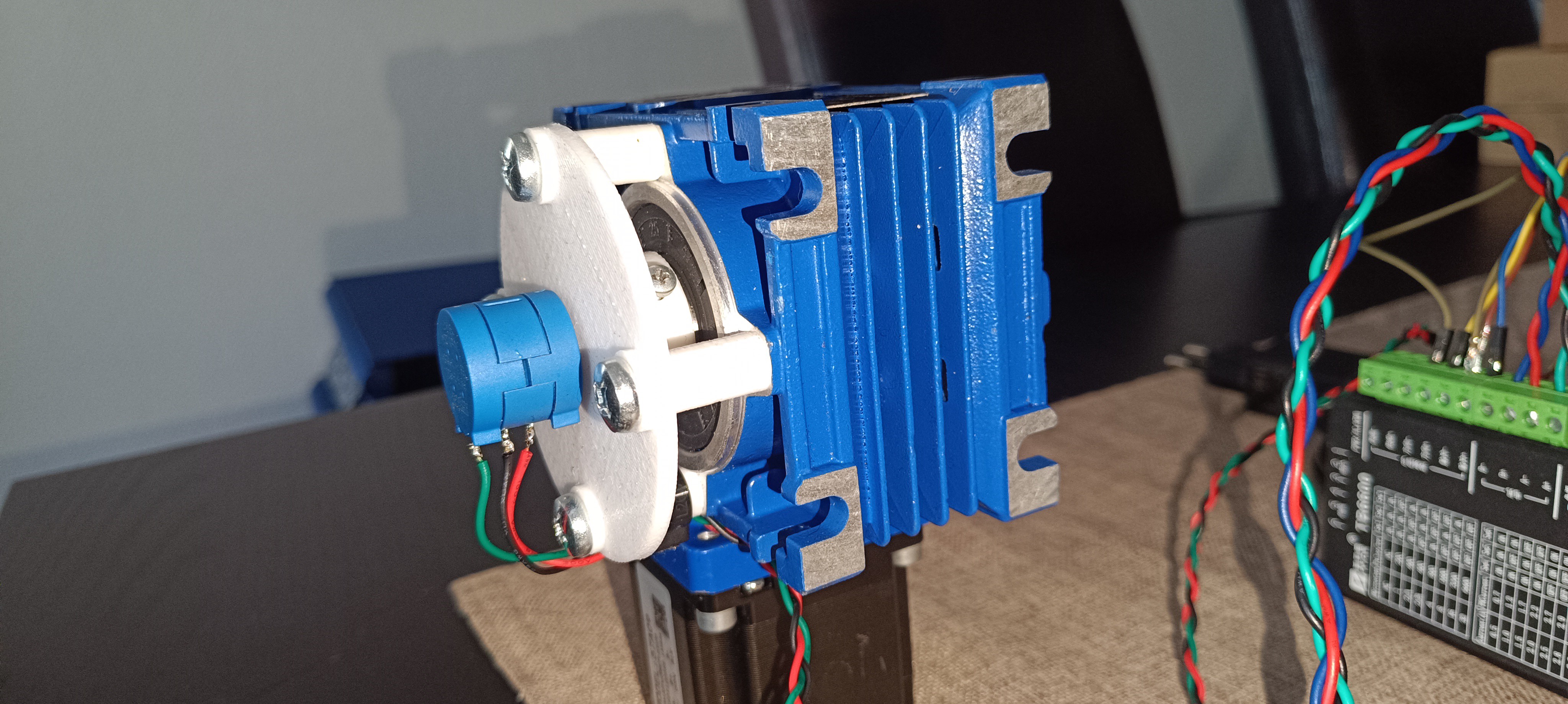
I 3D printed a plate with a hole in the middle for holding the potentiometer, and four holes on the side for mounting it on the gearbox with the help of some spacers to have enough space to fit in a 3D printed adapter that connects the potentiometer shaft to the gearbox's output. The potentiometer was now able to track the exact position of the gearbox over multiple rotations, and it was possible to use an Arduino Nano for controlling the stepper motor driver and reading the potentiometer to limit the gearbox's movement to a certain range.
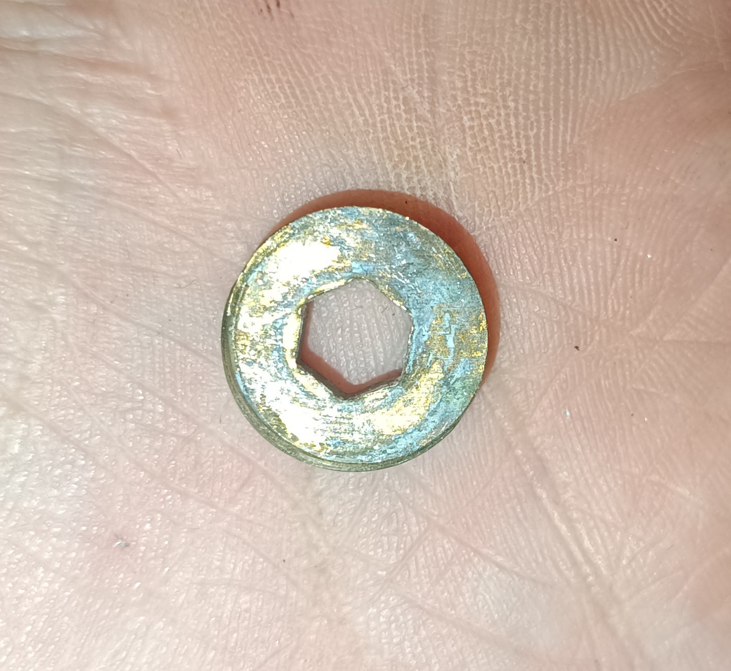
I uploaded some code to the Arduino that continuously moved the shaft two turns back and forth to see if everything kept working over a long time, and it turned out that the PLA shaft adapter failed after a while due to wear, so I had to buy one that was made out of steel. Because the steel adapter was made for an 8mm shaft, I had to use another stepper motor that I fortunately had lying around at home.
Once everything was working reliably, it was time to build some sort of adapter to connect the gearbox to the pressure regulator.

Normally, the pressure is adjusted by turning a custom screw with a hex key that compresses a spring.
While I haven't found out the exact thread size, I saw that it was very close to 3/8 inch BSP thread and it was possible to cut a 3/8 inch thread into the existing thread. With that, it was now possible to screw in a 3/8 inch fitting into the pressure regulator to compress the spring.
I tried to fit some fittings I had at home into the gearbox and the pressure regulator, and it looked like a 1/4 inch pipe connected to a 3/8 inch thread would fit in well.
So, I ordered some brass fittings and screws from which I could build an adapter.

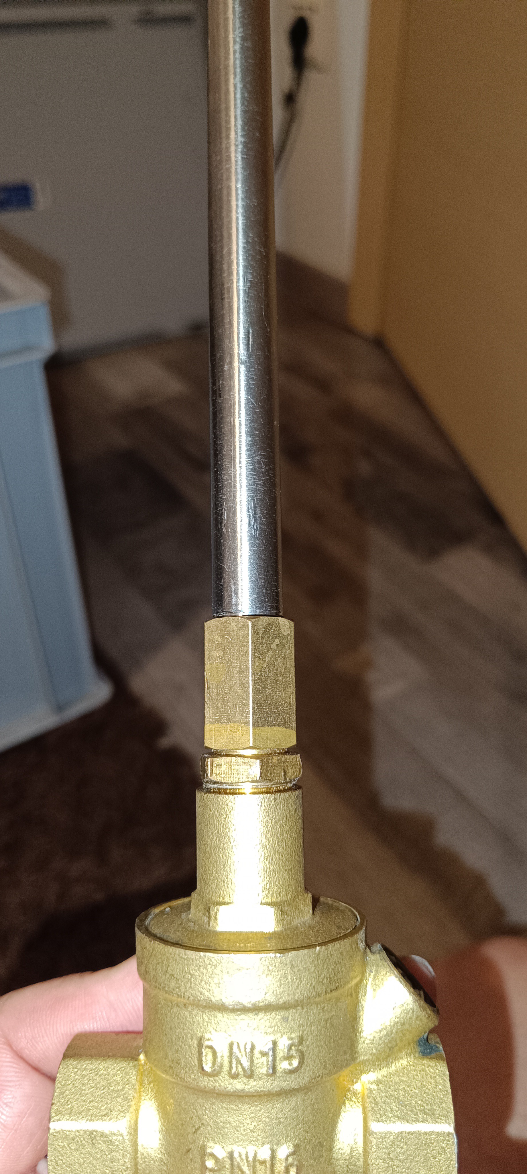
The adapter was made out of a 3/8 inch reducer fitting and a 1/4 inch pipe with a M5 thread cut in it for a screw that fit inside the keyway of the gearbox. All parts were soldered in place to prevent them from coming loose.
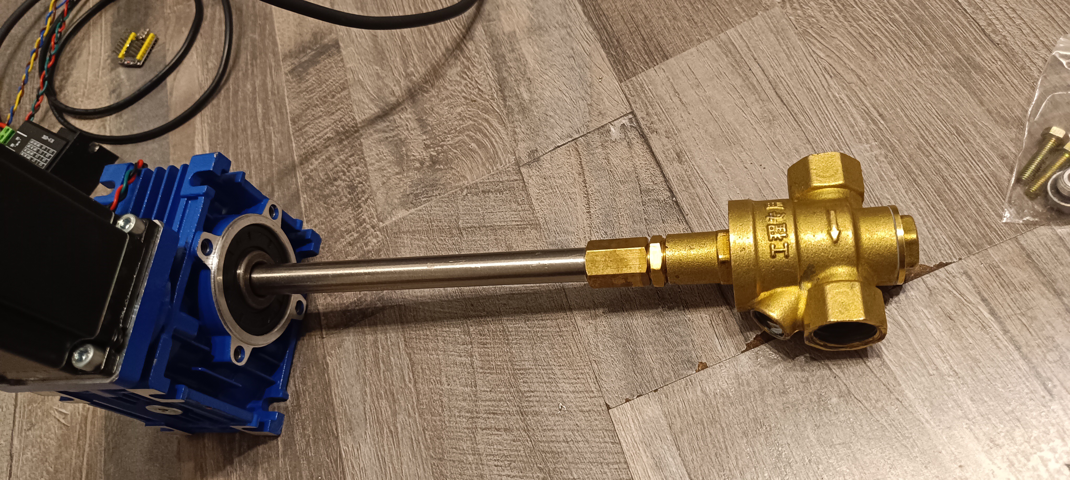
With the newly built adapter, it was possible to connect the gearbox and pressure regulator.

One note here:
Since the adapter essentially functions as a screw that moves in and out of the pressure regulator while adjusting the pressure, the assembly needs to be able to move freely in this direction. Currently, the assembly is mounted to the frame only with zip ties, so this is not a problem. However, if it is ever screwed to the frame in the future, it will be necessary to use a flexible coupler or another method of mounting the pressure regulator or gearbox that allows for some movement.
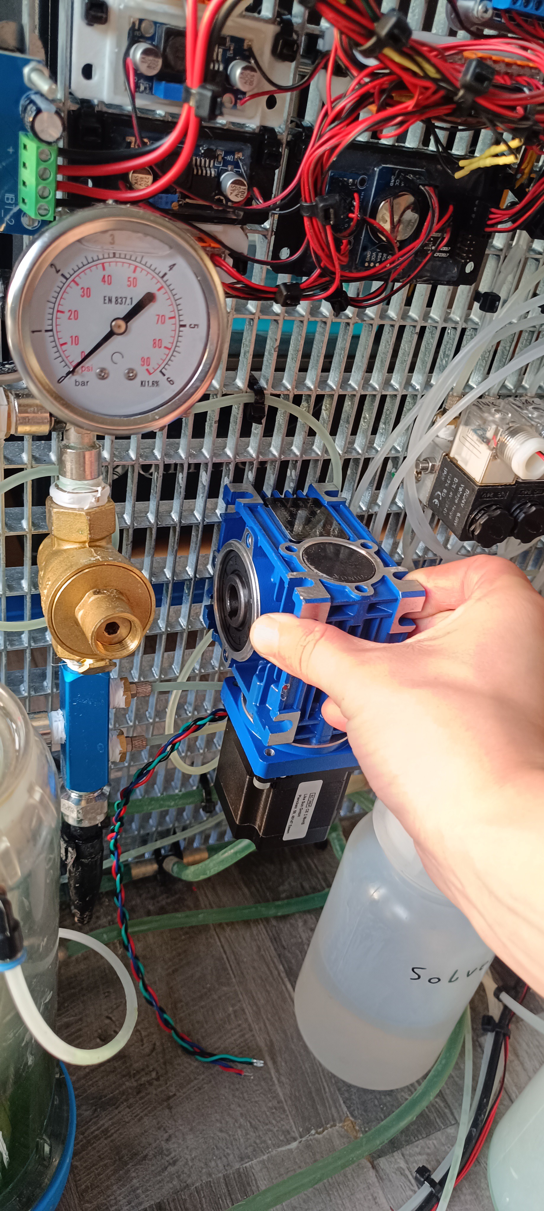
After mounting the gearbox, pressure regulator, stepper motor driver, and Arduino to the frame, it was time to add the necessary code to the printer controller for adjusting the pressure.

For that, I added a plus button for increasing the pressure, a minus button for decreasing the pressure, and an auto button which can be used to automatically adjust the pressure based on the TOF reading, in the future.

Finally, I added an optional small OLED display to the machine, which shows the current potentiometer reading, making it easy to see if there is a problem with the potentiometer.

With everything in place, I did some testing with the new motorized pressure regulator, and everything seems to work fine without any problems, so that it is now possible to adjust the ink pressure via software, which brings the project closer to being a fully functional CIJ printer.
Discussions
Become a Hackaday.io Member
Create an account to leave a comment. Already have an account? Log In.