Close
0%
0%

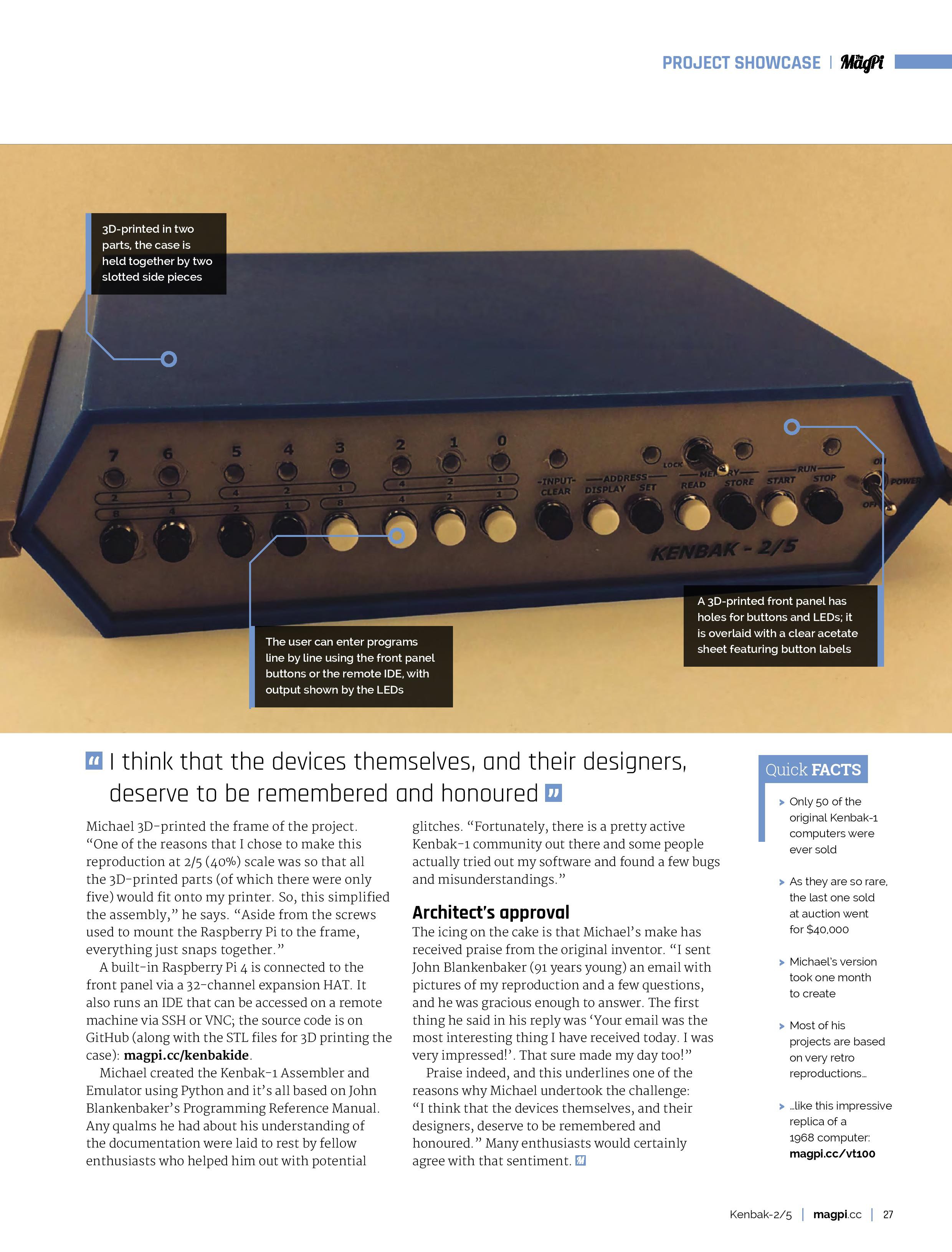
2:5 Scale KENBAK-1 Personal Computer Reproduction

Make a working reproduction of the venerable KENBAK-1 with a fully integrated development environment including an Assembler and Debugger.

Similar projects worth following

Background

If you have been following Hackaday for a while, you will have seen on numerous occasions the KENBAK-1, regarded by many as the first commercial personal computer.  Ten years ago Mark Wilson introduced KENBAK-uino, a reproduction running in emulation on an ATmega328. In 2016  posted a great writeup about John Blankenbaker KENBAK-1's creator. For a first hand account of the KENBAK-1 story you should really have a look at John Blakenbaker's own KENBAK-1 Computer site.

For a while you could purchase a full size KENBAK-1 Reproduction Kit, with a PCB, power supply, authentic metal case, 132 standard series TTL logic ICs as the CPU / process control logic (that's right no microprocessor) and two 1024 bit shift registers for memory.  Unfortunately this option is no longer available, but based on Mark Wilson's code Adwater & Stir offers a ruler sized nanoKENBAK-1, a half size µKENBAK-1 kit, and will soon be offering a full sized kit as well. In addition you can find KENBAK-1 emulators online like this one.

Motivation

So with all of this rightly deserved KENBAK-1 love out there, why am I creating yet another KENBAK-1 emulator?  The flip answer might be that I want to and I can, but that's not all of it. While all of the wonderful reproductions out there emulate the original to a tee and give a true KENBAK-1 experience, and even have some addition features like built in programs, at the end of the day you are still in many cases hand translating machine instructions and keying them in via the front panel buttons one step at a time.  And when something goes wrong, while you can step through your program one instruction at a time you only have visibility into one thing at a time on the front panel display, the instruction or a memory/register address. It gets old pretty fast. 

Where I think I can add some value is to integrate the machine code Emulator with an Assembler and a Debugger.  You will still be able to fire up my KENBAK-2/5 console to key and run your programs in native mode via the front panel. In addition you will be able to open an integrated development environment, enter in a KENBAK-1 program via assembly language and run said program using the actual console.  Similarly you will be able to step through your assembly code, set break points, and observe memory and register contents as you do. 

My other motivation for this project is that I really wanted to do a deep dive on this machine. When I looked at the Programming Reference Manual I was very impressed with the machine architecture and the instruction set. I mean an Indirect Indexed addressing mode on a machine built with logic chips. So cool.  

Design Considerations

  • The console itself will be rendered at 2:5 scale (hence the name KENBAK-2/5).  This is primarily so that all of the parts will fit onto the print bed of my Prusa MK3S.
  • A built in Raspberry Pi 4 will be connected to the front panel via a 32 channel port expander. In addition to running the KENBAK-1 Emulator, the extra horse power of the Pi will be required to run the "integrated development environment" (IDE).
  • The IDE will be accessed by connecting a display, keyboard, and mouse to the console's PI 4 itself or via VNC (preferred).
  • The Emulator, Assembler, and Debugger will be written in Python.

Hardware Required

In addition to the 3D printed parts you will require the following:

  • 1 Raspberry Pi 4 
  • 1 MCP23017 32 Channel I/O Expansion HAT (https://www.buyapi.ca/product/mcp23017-hat-32-channel-io-expansion-hat/)
  • 12 3mm LEDs (8 white and 4 yellow)
  • 2 Toggle switches (KINYOOO SPDT Mini Toggle, On/On 3 Pins 2 Position - Amazon)
  • 15 Push Button Switches (Mini 7mm Momentary (Off-ON) Push Button - Amazon - 8 black and 7 white)
  • Hook up wire. I used 22 AWG.
  • Female headers with 2.54 mm spacing.

Making the Console

The KENBAL-2/5 console has a 3D printed frame and uses panel mount components....

Read more »

  • Honey, somebody shrunk the Kenbak-1!

    Michael Gardi08/10/2021 at 00:46 0 comments

    I mentioned at the beginning of this project's Details that Adwater & Stir had some fine KENBAK-1 offerings. Based on Mark Wilson's code Adwater & Stir offers a ruler sized nanoKENBAK-1, a half size µKENBAK-1 kit, and will soon be offering a full sized kit as well. 

    Well I couldn't resist getting myself a nanoKENBAK-1. It comes fully assembled and tested.

    From tip to tip it's about 210 mm wide and 40 mm tall.  It's so cool to be able to program this ruler sized device, and as can be seen on the rear silk screen it includes both built in programs and the ability to store your own programs to EEPROM.

    I couldn't resist making a minimal case and stand. It sits on my desk now running the built in BCD clock program (it has a RTC chip).

  • My KENBAK-2/5 Was Featured in MagPi Magazine

    Michael Gardi08/03/2021 at 18:35 4 comments

  • Added a Disassembler

    Michael Gardi07/15/2021 at 20:09 0 comments

    I can't seem to stop wanting to improve my KENBAK-2/5 project, and anything that gets me "into the weeds" of the instruction set is especially appealing. To that end I have created a stand alone command line Disassembler. I have added the Python script to my GitHub repository and created a release.

    Here is the online help:

    usage: Disassemble a binary or delimited text file to KENBAK-1 source
           [-h] [-s] [-d] [-a] -f FILE
    
    optional arguments:
      -h, --help            show this help message and exit
      -s, --save            save the disassembly to a .asm file
      -d, --dump            dump the disassembly to standard out
      -a, --address         add the instruction address to each line
      -f FILE, --file FILE  file to disassemble

    Writing a disassembler is an interesting exercise, one that I had never undertaken before. Faced with an array of 256 raw bytes and trying to coax some meaningful structure out of it was pretty daunting. 

    The first thing I did was to determine which of the bytes represented the program code vs program data. Fortunately the first byte of code can be ascertained by looking at the fourth byte in memory which holds the PC (program counter/instruction pointer - defaults to 4). From that point, consecutive instructions can be readily resolved, that is until a "jump" instruction is encountered. By carefully following all of the jumps to other blocks of code you can create a map of all the code in the program.

    All of the non-code bytes are then assumed to be data. But which of those bytes represent constants vs data bytes that will be manipulated by the program.  Since all of the "registers" on a KENBAK-1  (A, B, X, PC, OUTPUT, AOC, BOC, XOC, and INPUT) are at fixed positions in memory that is a good place to start marking them as data bytes using a DB directive. The other bytes that will be written to can be determined by looking at all of the instructions that store to memory: STORE, SET, and JMK.  Everything else is then treated as a constant.

    Finally I did a pass to convert all of the memory references in the code to labels to make reading the emitted code a bit easier.

    To test the disassembler I input the 256 byte "Day of the Week.bin" file created by the IDE assembler and compared the assembly output to the original code that I wrote.  Furthermore I ran the disassembled code inside of the IDE to ensure that it indeed worked as expected. 

    Here is the original code:

    ; Program to calculate the day of the week for any date. To start this program you will
    ; have to input the date in four parts: Century, Year, Month, and Day. Each of the parts
    ; is entered as a two digit Binary Coded Decimal number (ie. the first digit will occupy 
    ; bits 7-4 as a binary number, and the second digit bits 3-0) using the front panel data
    ; buttons. The steps to run this program are:
    ;
    ; 1) Set the PC register (at address 3) to 4.
    ; 2) Clear the input data then enter the date Century.
    ; 3) Press Start.
    ; 4) Clear the input data then enter the date Year.
    ; 5) Press Start.
    ; 6) Clear the input data then enter the date Month.
    ; 7) Press Start.
    ; 8) Clear the input data then enter the date Day.
    ; 9) Press Start.
    ;
    ; The day of the week will be returned via the data lamps using the following encoding:
    ; 
    ;      7-Sunday 6-Monday 5-Tuesday 4-Wednesday 3-Thursday 2-Friday 1-Saturday
    ;
    ; All lamps turned on means the last item entered was invalid and you have to restart.
    ;
    ;
    ; Get the date we want the day for.
    ;
        load    A,INPUT         ; Get the century.
        jmk 	   bcd2bin
        store   A,century
        halt
        load    A,INPUT         ; Get the year.
        jmk     bcd2bin
        store   A,year
        halt
        load    A,INPUT         ; Get the month.
        jmk     bcd2bin
        sub     A,1			    ; Convert from 1 based to 0 based.
        store   A,month
        halt
        load    A,INPUT         ; Get the day.
        jmk     bcd2bin
        store   A,day
        load    A,0b10000000    ; Setup the rotation pattern.
        store   A,rotate
    ; 
    ; All the inputs should be in place. Start the conversion.
    ;
        load    A,year          ; Get the year.
        sft 	   A,R,2           ; Divide by 4.
        store   A,B             ; Save to B the working result.
        add     B,day           ; Add the day of the month.
     load...
    Read more »

  • OK Another One More Thing

    Michael Gardi07/06/2021 at 23:46 0 comments

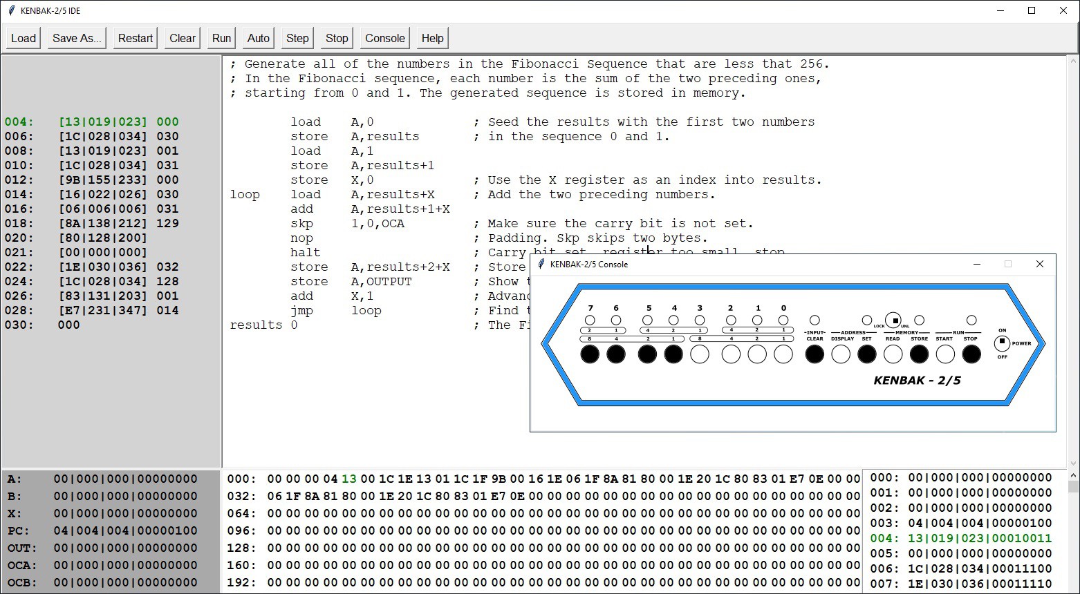
    I realize that not too many people are going to make a physical KENBAK-1 reproduction, but I really want people to experience Bob Blankenbaker's creation should they desire to. So, I created a simulator that is integrated into my KENBAK-2/5 IDE. Not much to say here. The simulator appears as a pop-up window when you click the Console button.

    Here is a demonstration of the console simulator running my Fibonacci program written in KENBAK-1 assembler.

    I have added a new script KENBAK_IDE_With_Console.py to my GitHub repository as I didn't want to alter the non Console version until I have done more testing. I'll combine the two in a bit. This script also requires the Front Panel Text Colored.png image.

    Update 07/08/2021: I have integrate the Console into the main script now and created a release.

  • A Reply from John Blankenbaker

    Michael Gardi05/15/2021 at 15:23 0 comments

    Over on Instructables GilDev, who also did a wonderful KENBAK-1 Replica, suggested "Feel free to send photos of your creation to John Blankenbaker, he replied to my mails and was very kind!"  So I did and he was. The first thing he said in his reply "Your email was the most interesting thing I have received today. I was very impressed!". Sure made my day too!

    As part of my Email I said the following, "I also wrote a Day of the Week program. It took me 251 bytes to write. If I understand what you said in the VCF East keynote you gave in 2016, Day of the Week was one of three programs that you had simultaneously loaded into memory for demonstration purposes. Amazing!". 

    Here is his reply. 

    You overestimated my capability in programming the day of the week problem. I did it only for the 20th century. One reason for limiting it was the problem becomes more complicated very quickly since the English jumped ahead 12 days in 1753 to come into agreement with the European calendars. One of the interesting side aspects of demonstrating this problem was that most people could only verify two dates/day of the week. The were Pearl Harbor and their marriage day. Another interesting point is that only about half of the high school math teachers could quote the rules for
    skipping dates in the calendar. My most complex program was for three dimensional tic-tac-toe on a 4 x 4 x 4 board. When the program was done, it did not have enough memory left to recognize the end of the game.

    I was so nice of John Blankenbaker to take the time to reply.

  • One More Thing

    Michael Gardi05/07/2021 at 19:34 0 comments

    When John Blankenbaker was demonstrating his KENBAK-1 Personal Computer back in 1971, one of the programs he always showed was a Day of the Week calculator. Given any date, it can tell you what day of the week that date fell on. It was something that was pretty cool that everyone could relate to.

    Well I didn't feel that my KENBAK-2/5 reproduction would be quite complete until it could do the same. It was a fun programming challenge that exercised a lot more of the capabilities of my machine, and in fact uncovered a few minor issues with my emulator software:

    • JMK operand was not saving the return address correctly
    • HALT operand needed to advance the program counter (PC)
    • I tweaked some of the console interactions.
    • I added a DB directive to reserve a byte of memory.

    I feel a lot more confident now that my reproduction is a very close work-a-like to the original.  Here is the code:

    ; Program to calculate the day of the week for any date. To start this program you will
    ; have to input the date in four parts: Century, Year, Month, and Day. Each of the parts
    ; is entered as a two digit Binary Coded Decimal number (ie. the first digit will occupy 
    ; bits 7-4 as a binary number, and the second digit bits 3-0) using the front panel data
    ; buttons. The steps to run this program are:
    ;
    ; 1) Set the PC register (at address 3) to 4.
    ; 2) Clear the input data then enter the date Century.
    ; 3) Press Start.
    ; 4) Clear the input data then enter the date Year.
    ; 5) Press Start.
    ; 6) Clear the input data then enter the date Month.
    ; 7) Press Start.
    ; 8) Clear the input data then enter the date Day.
    ; 9) Press Start.
    ;
    ; The day of the week will be returned via the data lamps using the following encoding:
    ; 
    ;      7-Sunday 6-Monday 5-Tuesday 4-Wednesday 3-Thursday 2-Friday 1-Saturday
    ;
    ; All lamps turned on means the last item entered was invalid and you have to restart.
    ;
    ;
    ; Get the date we want the day for.
    ;
    	load	A,INPUT			; Get the century.
    	jmk	bcd2bin
    	store 	A,century
    	halt
    	load	A,INPUT			; Get the year.
    	jmk	bcd2bin
    	store	A,year
    	halt
    	load	A,INPUT			; Get the month.
    	jmk	bcd2bin
    	sub	A,1			; Convert from 1 based to 0 based.
    	store	A,month
    	halt
    	load	A,INPUT			; Get the day.
    	jmk	bcd2bin
    	store	A,day
    	load	A,0b10000000		; Setup the rotation pattern.
    	store	A,rotate
    ; 
    ; All the inputs should be in place. Start the conversion.
    ;
    	load 	A,year			; Get the year.
    	sft	A,R,2			; Divide by 4.
    	store	A,B			; Save to B the working result.
    	add	B,day			; Add the day of the month.
    	load	X,month			; Use X as index into the month keys.
    	add	B,monkeys+X		; Add the month key.
    	jmk	leapyr			; Returns a leap year offset in A if applicable.
    	jmk	working			; Working...
    	sub	B,A			; Subtract the leap year offset.
    	jmk     cencode			; Returns a century code in A if applicable.
    	jmk	working			; Working...
    	add 	B,A			; Add the century code.
    	add	B,Year			; Add the year input to the working result.
    chkrem	load	A,B			; Find the remainder when B is divided by 7.
    	and	A,0b11111000		; Is B > 7?
    	jmp	A,EQ,isseven		; No then B is 7 or less.
    	sub	B,7			; Yes then reduce B by 7.
    	jmk	working			; Working...
    	jmp	chkrem			; Check again for remainder.
    isseven load		A,B		; Is B = 7?
    	sub	A,7			; Subtract 7 from B value.
    	jmp	A,LT,gotday		; No B is less than 7.
    	load	B,0			; Set B to zero because evenly divisible.
    gotday	load	X,B			; B holds the resulting day number.	Use as index.
    	load	A,sat+X			; Convert to a day lamp.
    	store	A,OUTPUT
    	halt
    error	load	A,0xff			; Exit with error
    	store	A,OUTPUT		; All lamps lit.
    	halt
    
    ;
    ; Store inputs.
    ;	
    century db
    year	db
    month	db	
    day	db
    
    ;
    ; Static table to hold month keys.
    ;
    monkeys	1				
    	4
    	4
    	0
    	2
    	5
    	0
    	3
    	6
    	1
    	4
    	6
    
    ;
    ; Need to preserve A while performing some steps.
    ;
    saveA	db	
    
    ;
    ; Subroutine to blink the lamps to indicate working.
    ; 
    rotate	db				; Pattern to rotate.
    working	db				; Save space for return adderess.
    	store	A,saveA			; Remember the value in A.	
    	load	A,rotate		; Get the rotate pattern.
    	store	A,OUTPUT		; Show the...
    Read more »

  • Finishing Up

    Michael Gardi04/28/2021 at 19:13 0 comments

    I did some additional testing of the IDE and added a Help button to popup some information on the assembly syntax.

    I made a video where I try to demonstrate how the KENBAK-2/5, with it's built in Raspberry Pi, does a good job as a KENBAK-1 reproduction. As with the original you can enter and run programs, and view internal machine memory, just using the switches, buttons, and lamps on the front panel of the console.

    But in addition, using the power of the Raspberry Pi 4 to implement an Integrated Development Environment, you can key in programs using native KENBAK-1 assembly language.  With breakpoints, single step modes, and memory visualizations, debugging suddenly become a lot easier.  

    When I first looked at the KENBAK-1 Programming Reference Manual I was very impressed with the instruction set for a machine with no microprocessor, just discrete logic chips. Implementing an Assembler and Emulator only served to deepen my appreciation for what  John Blankenbaker created.

  • Running the KENBAK-2/5 IDE

    Michael Gardi04/26/2021 at 15:39 0 comments

    Running the KENBAK-1 IDE

    The KENBAK-IDE.py file is available from my GitHub repository.  If used outside of the KENBAK-2/5 hardware environment, it should run on any machine that supports Python3 without any library dependencies. In this mode you can still write, debug, and run KENBAK-1 assembly language programs. It's a great learning environment all by itself.

    If you are running on the KENBAK-2/5's Raspberry Pi with the port extender hat you will have to first make sure that the wiringpi library is installed.

    pip3 install wiringpi

    I created a folder on the Pi

    mkdir /home/pi/KENBAK-1

    and copied the KENBAK-IDE.py file there. Then its a simple matter of running the Python script.

    cd /home/pi/KENBAK-1
    python3 KENBAK-IDE.py

    Auto Start the KENBAK-1 IDE

    If you are running KENBAK-1 IDE as a dedicated console on the built-in Raspberry Pi like I am it's convenient to have the program start automatically when the machine boots. Here is what I did to make this happen.

    I created an autostart folder on my Pi and switched to that folder.

    mkdir /home/pi/.config/autostart
    cd /home/pi/.config/autostart

    Into the autostart folder just created I added the following two files.

    runKENBAK-1

    cd /home/pi/KENBAK-1
    /usr/bin/python3 KENBAK-IDE.py

    KENBAK-1.desktop

    [Desktop Entry]
    Type=Application Name=KENBAK-1
    Exec=/home/pi/.config/autostart/runKENBAK-1 

    In addition the runKENBAK-1 file must be made executable with the following command:

    chmod 777 runKENBAK-1

    Now if you reboot the system, you should briefly see the desktop appear, and shortly after KENBAK-IDE application will load.

    Setting up VNC

    Current Raspberry Pi OS versions have RealVNC baked in.  If you are running the Raspberry Pi in the KENBAK-2/5 console headless as I am you have to setup a virtual desktop for the VNC client to connect to. The easiest way I have found to do this is to add the following lines to the end of the /etc/rc.local file before the exit 0 on the Pi.

    # Setup a virtual screen for the VNC server.
    sudo -u pi vncserver -randr=1920x1080
    

    Set the screen dimension to be the same as the machine that you will be accessing the KENBAK-IDE from. You should then be able to connect to the KENBAK-2/5 with a RealVNC client at the machines IP address with a :1 appended, for example in my case 192.169.123.122:1.

  • Lots of Progress

    Michael Gardi04/25/2021 at 23:03 0 comments

    I have integrated the Console functionality (being able to read the buttons and show the lamps ) with the Emulator.  With just this in place I now have a fully functional KENBAK-1. I can load and run programs and view memory locations from the front panel as described in the Programming Reference Manual and Laboratory Exercises.  

    But that's not all I wanted to accomplish. With the further integration of my KENBAK-1 Assembler, the IDE that I had envisioned for this project is really taking shape.  As can be seen in a previous log, the Assembler has no "passes". The assembler instructions are continuously parsed as you type and when the corresponding binary code no longer has any question marks you know the syntax for the line is correct.  It all works quite well.

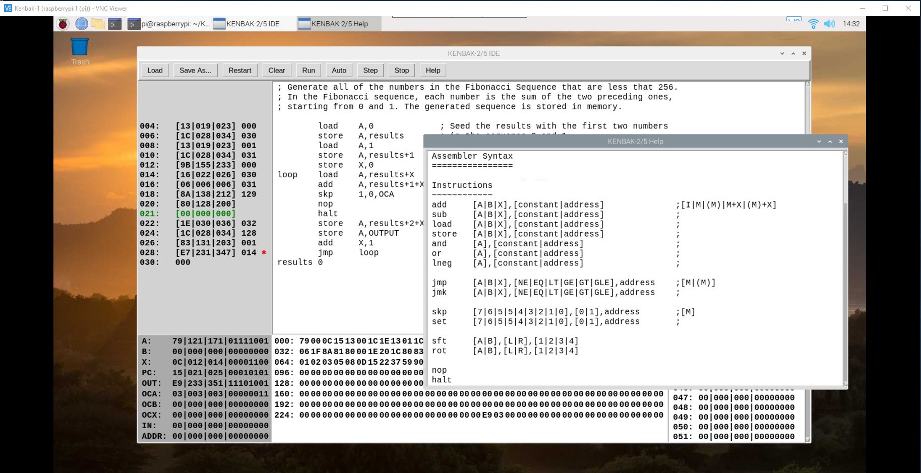
    I'm running the Raspberry Pi 4 inside my reproduction headless, but when I VNC into it, this is what I see.

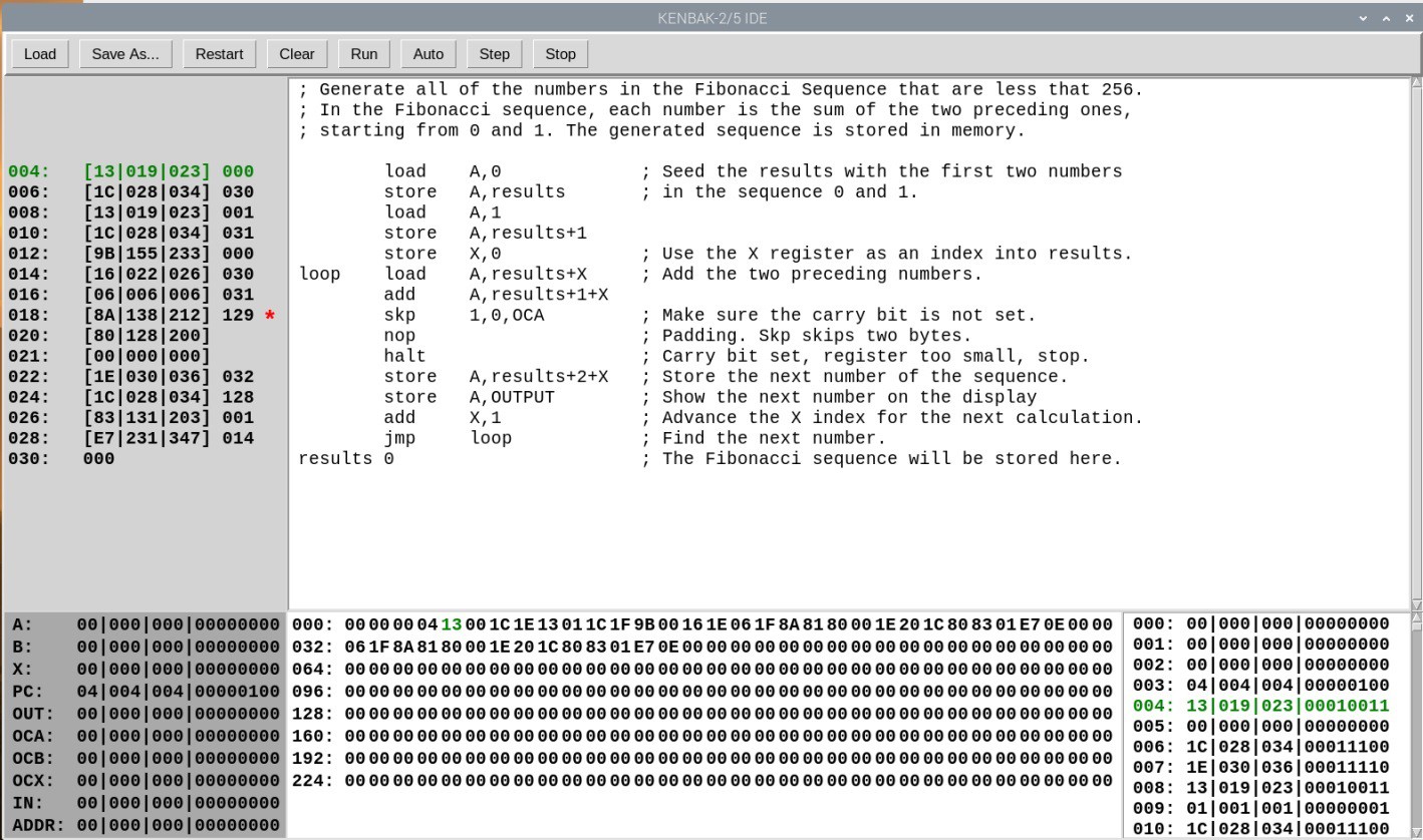
    Here I have just loaded the Fibonacci program seen in previous logs. The upper right quadrant is of course the assembler code and to it's left the  equivalent binary instructions. By clicking on the binary instructions you can set or clear breakpoints (the skp instruction has a breakpoint set for instance).

    To the lower left is the state of the predefined "registers" including the address register which is  used to load and read memory locations.  Middle bottom is a hex dump of all 256 memory locations, and lower right shows the same memory locations in more detail with hex, decimal, octal and binary representations for each location.  All references to memory locations are in decimal (leftmost columns in the instruction, hex dump, and details panels and rightmost column in the instruction panel). 

    The entries rendered in green represent the memory location currently pointed to by the program counter (PC). 

    The front panel console is fully integrated with the IDE. So for instance you could start the Fibonacci program shown above by pressing the physical START button on the console or by clicking the Run button in the IDE. Similarly pressing and holding the STOP button and then pressing START will perform a single step as will the IDE's Step button.  

    Anything written to the OUTPUT register will show up on the data lamps on the console.  Data stored from the console to memory locations through the address register will be reflected in the IDE.  

    The IDE does offer some additional features. Your programs can be saved and loaded to disk (the assembler code and the binary memory image both). The  Restart button will reset everything to the last loaded image. Clear will zero out memory and the assembler program space then set the PC to memory location 4. Auto will run the program at a rate of about one instruction per second.

    You can debug your program by single stepping or by setting breakpoints and observing the memory and registers.

    If you just want to play around with KENBAK-1 code, you can run the IDE "standalone" on any platform that supports Python, but of course you will only be able to integrate the KENBAK-2/5 console on a Raspberry Pi since it's bound to the wiringpi library. 

    Over the next couple of days I'm going to try and put together a video of all of this in action. 

  • We Have Blinkenlights!

    Michael Gardi04/17/2021 at 17:18 3 comments

    With the wiring complete I wrote a small program in Python to test the lights, buttons, and switches on the front panel. To be clear this is NOT the KENBAK-2/5 emulator running a program (yet). 

    As it turns out I did have to replace one of the LEDs which wasn't working.

    The Python script communicates with the MCP23017 32 Channel I/O Expansion HAT through the Python wiringpi library. Here is the code for my test program. 

    #!/usr/bin/python
    
    import wiringpi as wiringpi
    from time import sleep
    
    # Set the base number of ic1.
    ic1_pin_base = 65
    # Pin number to code number:
    # 1 = 65, 2 = 66, 3 = 67, 4 = 68, 5 = 69, 6 = 70, 7 = 71, 8 = 72, 9 = 73, 10 = 74, 11 = 75, 12 = 76, 13 = 77, 14 = 78, 15 = 79, 16 = 80
    
    # Define the i2c address of ic1.
    ic1_i2c_addr = 0x24
    
    # Set the base number of ic2.
    ic2_pin_base = 81
    # Pin number to code number:
    # 1 = 81, 2 = 82, 3 = 83, 4 = 84, 5 = 85, 6 = 86, 7 = 87, 8 = 88, 9 = 89, 10 = 90, 11 = 91, 12 = 92, 13 = 93, 14 = 94, 15 = 95, 16 = 96
    
    # Define the i2c address of ic2.
    ic2_i2c_addr = 0x20
    
    # Initialize the wiringpi library.
    wiringpi.wiringPiSetup()
    # enable ic1 on the mcp23017 hat
    wiringpi.mcp23017Setup(ic1_pin_base,ic1_i2c_addr)
    # enable ic2 on the mcp23017 hat
    wiringpi.mcp23017Setup(ic2_pin_base,ic2_i2c_addr)
    
    # Setup led pins.
    light_stop = 65
    light_store = 66
    light_set = 67
    light_clear = 68
    
    light_0 = 73
    light_1 = 74
    light_2 = 75
    light_3 = 76
    light_4 = 77
    light_5 = 78
    light_6 = 79
    light_7 = 80
    
    # Setup toggle pins.
    toggle_off = 69
    toggle_on = 70
    toggle_unl = 71
    toggle_lock = 72
    
    # Setup button pins
    button_stop = 81
    button_start = 82
    button_store = 83
    button_read = 84
    button_set = 85
    button_display = 86
    button_clear = 87 
    
    button_0 = 89
    button_1 = 90
    button_2 = 91
    button_3 = 92
    button_4 = 93
    button_5 = 94
    button_6 = 95
    button_7 = 96
    
    # Set the pin mode to an output for all the leds.
    wiringpi.pinMode(light_stop,1)
    wiringpi.pinMode(light_store,1)
    wiringpi.pinMode(light_set,1)
    wiringpi.pinMode(light_clear,1)
    wiringpi.pinMode(light_0,1)
    wiringpi.pinMode(light_1,1)
    wiringpi.pinMode(light_2,1)
    wiringpi.pinMode(light_3,1)
    wiringpi.pinMode(light_4,1)
    wiringpi.pinMode(light_5,1)
    wiringpi.pinMode(light_6,1)
    wiringpi.pinMode(light_7,1)
    
    # Set all the leds off to start with.
    wiringpi.digitalWrite(light_stop,0)
    wiringpi.digitalWrite(light_store,0)
    wiringpi.digitalWrite(light_set,0)
    wiringpi.digitalWrite(light_clear,0)
    wiringpi.digitalWrite(light_0,0)
    wiringpi.digitalWrite(light_1,0)
    wiringpi.digitalWrite(light_2,0)
    wiringpi.digitalWrite(light_3,0)
    wiringpi.digitalWrite(light_4,0)
    wiringpi.digitalWrite(light_5,0)
    wiringpi.digitalWrite(light_6,0)
    wiringpi.digitalWrite(light_7,0)
    
    
    # Set the pin mode to an input for all the switches and buttons.
    wiringpi.pinMode(toggle_off,0)
    wiringpi.pinMode(toggle_on,0)
    wiringpi.pinMode(toggle_lock,0)
    wiringpi.pinMode(toggle_unl,0)
    
    wiringpi.pinMode(button_stop,0)
    wiringpi.pinMode(button_start,0)
    wiringpi.pinMode(button_store,0)
    wiringpi.pinMode(button_read,0)
    wiringpi.pinMode(button_set,0)
    wiringpi.pinMode(button_display,0)
    wiringpi.pinMode(button_clear,0)
    wiringpi.pinMode(button_0,0)
    wiringpi.pinMode(button_1,0)
    wiringpi.pinMode(button_2,0)
    wiringpi.pinMode(button_3,0)
    wiringpi.pinMode(button_4,0)
    wiringpi.pinMode(button_5,0)
    wiringpi.pinMode(button_6,0)
    wiringpi.pinMode(button_7,0)
    
    # Enable the internal pull-ups on all the inputs
    wiringpi.pullUpDnControl(toggle_off,2)
    wiringpi.pullUpDnControl(toggle_on,2)
    wiringpi.pullUpDnControl(toggle_lock,2)
    wiringpi.pullUpDnControl(toggle_unl,2)
    
    wiringpi.pullUpDnControl(button_stop,2)
    wiringpi.pullUpDnControl(button_start,2)
    wiringpi.pullUpDnControl(button_store,2)
    wiringpi.pullUpDnControl(button_read,2)
    wiringpi.pullUpDnControl(button_set,2)
    wiringpi.pullUpDnControl(button_display,2)
    wiringpi.pullUpDnControl(button_clear,2)
    wiringpi.pullUpDnControl(button_0,2)
    wiringpi.pullUpDnControl(button_1,2)
    wiringpi.pullUpDnControl(button_2,2)
    wiringpi.pullUpDnControl(button_3,2)
    wiringpi.pullUpDnControl(button_4,2)
    wiringpi.pullUpDnControl(button_5,2)
    ...
    Read more »

View all 15 project logs

Enjoy this project?

Share

Discussions

martinoswald8364 wrote 10/12/2021 at 12:04 point

Finally a 2:5 Scale KENBAK-1 project with lots of interesting features. 

https://www.marriagecounselingoffortworth.com

  Are you sure? yes | no

zpekic wrote 05/18/2021 at 04:44 point

I knew that KENBAK-1 existed but didn't look deeper into its architecture - until now. While the memory is really small, the instruction set is very powerful for the era and the "price point", more powerful in my opinion than a PDP-8 from which some inspiration is derived (e.g. storing the return address in the location before the start of the subroutine. Interestingly, it could be extended to become 16-bit computer with 16-bit words (and addresses, meaning 64k words of memory) with minimal changes. 

  Are you sure? yes | no

Michael Gardi wrote 05/18/2021 at 07:23 point

It was definitely the machine’s architecture that drew me to this project and defined the direction I took creating the integrated assembler. Having written a couple of KENBAK-1 programs now I can tell you that the instruction set is really great to work with. Boy a 16-bit KENBAK-2 would have been awesome!

  Are you sure? yes | no

zpekic wrote 05/20/2021 at 03:44 point

I looked a bit, and the easiest approach would be to extend regs to 16 bits, use 16-bit wide memory (no bytes, only word read/write). The only drawback would be that each instruction word would have half unused. I think my microcode compiler (see example here: https://github.com/zpekic/Sys_180X/blob/master/CDP180X/CDP180X.mcc) would probably generate half of the CPU logic in VHDL, given the orthogonal and logical instruction set. I think it would be possible to implement a "switch" and flip the CPU from 8 to 16 bits! Of course, it would just be a machine executing KENBAK-1 instruction set, but internally would be a different beast. A data-path processor with "real" A,B,X,P,OF,CY registers. Memory interface unit your intercept reads from locations and return right reg value instead, and write to those locations would be routed to registers. Performance would probably be 10X at the same speed. The only missing feature of KENBAK is no interrupts? Unless I missed them in the documentation. 

On second thought, it would be more true to the original to have real memory mapped registers. This way the state of the machine can be fully controlled from the outside by updating the memory (the idea behind the LED/switch console, which can also be kept simple this way). Memory mapped registers were more common back in the (minicomputer) era, for example TMS9900 (used WP real internal register to set the base address, KENBAK simply hard-codes the base address). In that case, internally probably 3 registers (8 or 16 bit long, as the machine would be parallel not serial) would be sufficient. Skimming through the documentation looks like this is number KENBAK had too: I (instruction), W, and K (temp for data / address).

  Are you sure? yes | no

Cees Meijer wrote 04/07/2021 at 14:18 point

As a retro computer enthousiast I certainly heard of the KENBAK. And also thought about making a replica like this. Yours looks realy great !. Do you intend to publish the 3D design ?

  Are you sure? yes | no

Michael Gardi wrote 04/07/2021 at 15:34 point

Hello. I just posted the design files for the case to GitHub and added a link to them in this project. The software is still a few weeks away.  Thanks for your interest.

  Are you sure? yes | no

Dan Maloney wrote 04/06/2021 at 17:19 point

And here I was thinking I knew all the cool computers from the first wave of the hobbyist PC revolution. But I'd never heard of this one. Nice looking machine -- I'll have to dig into it a little more.

Looking forward to more details on the repro!

  Are you sure? yes | no

Michael Gardi wrote 04/06/2021 at 18:26 point

This one kinda slipped under my radar too. I'm enjoying my deep dive into the inner workings of the KENBAK-1. An interesting piece of personal computing history for sure.

  Are you sure? yes | no

Michael Gardi wrote 05/12/2021 at 22:10 point

Pretty much finished with this project now Dan. Curious what you think?

  Are you sure? yes | no

Similar Projects

Does this project spark your interest?

Become a member to follow this project and never miss any updates