The Emulator for my KENBAK-2/5 Reproduction simulates in software the operation of the 132 integrated circuits that made up the original KENBAK-1's hardware. It accepts as input a 256 byte array that represents the entire block of memory that was in a KENBAK-1 and executes the instructions encoded into those bytes until a HALT instruction is encountered.
While an Assembler takes the symbolic representation of an instruction like LOAD A,1 and converts it into two byte codes 0x13 and 0x01, the emulator recognizes that 0x13 means load the A register with the byte that immediately follows the op code being executed (0x13) and alters the value of the A register to be a 1.
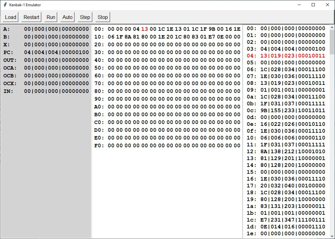
So here is a picture of my KENBAK-2/5 Emulator loaded with the byte codes produced by running my Assembler on the Fibonacci sequence program from the previous log entry.

On this screen we can see:
- Left - The values of nine special memory locations in the KENBAK-1;
Name Address Usage A 000 A register. B 001 B register. X 002 C register. PC 003 Program counter. OUT 129 Maps to front panel data display lamps. OCA 130 Overflow/Carry bits for A register. OCB 131 Overflow/Carry bits for B register. OCX 132 Overflow/Carry bits for C register. IN 255 Maps to the front panel data input button - Middle - A hex based overview of the 256 bytes of KENBAK-1 memory.
- Right - A more detailed view of the memory bytes in hex, digital, octal, and binary representations.
Here is a short video of the Emulator in action.
 Michael Gardi
Discussions
Become a Hackaday.io Member
Create an account to leave a comment. Already have an account? Log In.