My first experiments with touch pcbs went pretty well so I figured I'd move on to making something more ... complex and interesting. A little backstory, my sister is the more musically inclined one in our family so when she was young she took piano lessons for a number of years and she was very good at it. Every year for her birthday I make her something so I figured this year it would be something musical, specifically related to the piano.
Her bday isn't till September so that gives me plenty of time but I figured that my recent interest in touch sensing could be combined with my recent audio experimentation in my UV timer controller project (where I played with custom beeps played through a piezo when the timer went off). So what better project than a touch piano! I'm just hoping that she doesn't read my project posts or watch my videos :-) in the meanwhile.
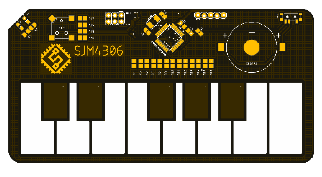
The first step was to design a pcb using what I've learned in the last log. Here's the design I came up with:

I tried to keep the key size and spacing reasonable for a human sized finger. I also wanted to keep everything as thin/flat as possible so I opted for all surface mount components, including the speaker (a magnetic one, but a piezo would work as well). I opted for a CR2032 to provide power with one of those thin metal battery holders that can simply be directly soldered to the pcb. To round out the features/components I use my goto atmega328p, two leds to indicate power and button presses and finally a small slide power switch. I did think about doing soft power control either using a momentary button (to minimize power draw) or another touch button but figured I'd keep things simple and just use a switch. Other than that I added two header spots, one is for icsp in case I needed to flash the bootloader/fuses on a new chip and the second is a serial port for programming using a cheap usb serial dongle. I think in the next board revision I'll add these hidden on the other side to interface with a pogo adapter so they aren't visible on top.
So now I had a pcb designed and a reliably working touch sensing library. While I wait for the boards to be manufactured and sent from China I proceeded with the next step which was to tackle the rest of the software. I first started with the beep/bloop software I'd written for my UV timer controller project had some serious limitations. For starters it was really meant for playing preprogrammed tunes so it was blocking (meaning nothing else could run while playing), and also it could only play one note at a time.
I could just throw a single timer at each channel (the atmega328p has three timers), but that would only net me three channels and regular delays that rely on timer0 would stop working accurately. I needed a software solution.
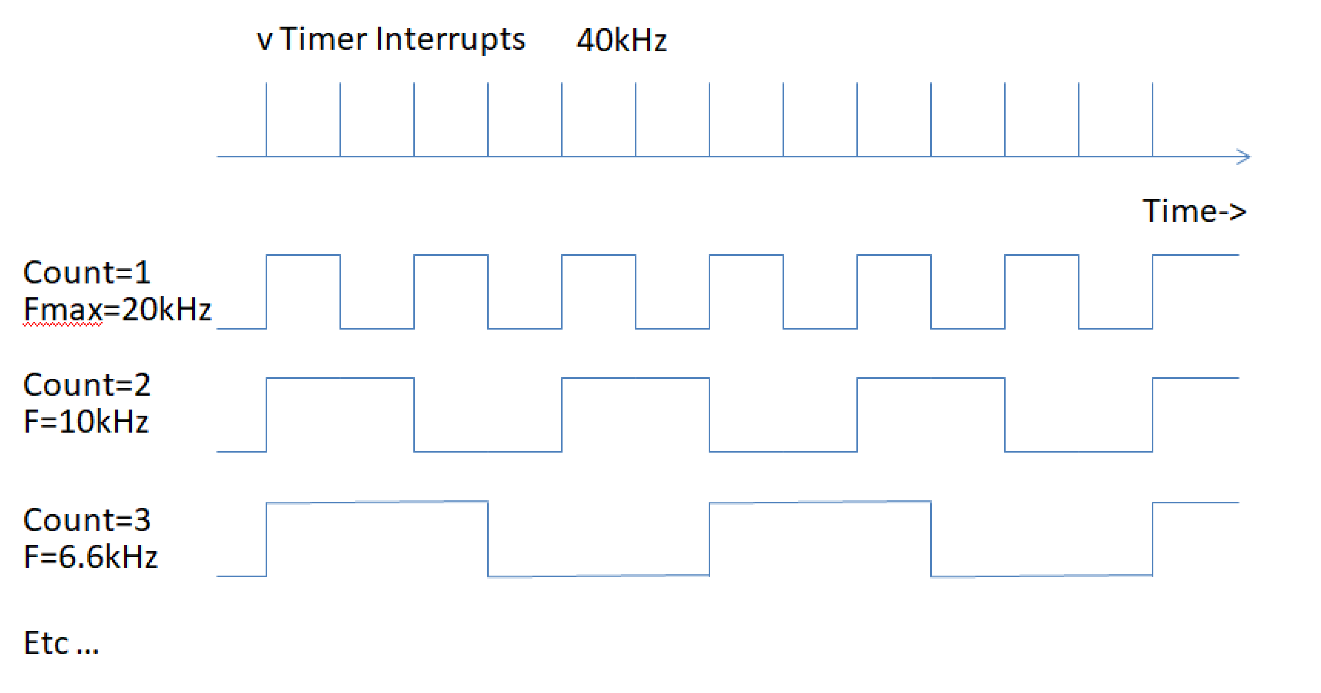
To address this I knew I had to move the squarewave generation to use an interrupt. Since the human hearing range is specified to be around 20kHz I set that as my upper end. This meant I had to use at least a 40kHz interrupt (since one period of a squarewave requires two edge changes). Below is a little diagram I drew up to demonstrate how the interrupt and output frequency generation would work.
 I wanted at least 4 channels to be playable simultaneously (based more on the gpio I had available after deciding I wanted one full octave of keys). To achieve this, each channel has a counter, compare value, and an enable/disable bit. Each time the interrupt is executed it checks if each channel's count is equal to the compare value for that channel. If not then it increments it and does nothing to the output pins for that channel. If so then it clears the count and if the enable/disable bit is set it toggles the output pin. To ensure this all works properly the time spent in the interrupt must be fairly short. Executing at 40kHz I measured the interrupt execution time to be around 8us out of the available 25us period (meaning it consumes ~32% of the cpu processing time). If I wanted to add more channels this would become a limiting factor, but for 4 channels it was acceptable.
Another obvious limitation is that up near the max frequency you can see varying the count compare value is very coarse (going from 1 to 2 and 2 to 3 varies the frequency by many kHz and cannot generate frequencies between). This means for practicality, this method is limited to generating output frequencies of around 1kHz and below with reasonable resolution.
So now I can generate 4 independent squarewaves output on any pin I want. To be able to control this I wrote a function called beep which converts the frequency of the desired note (I found a table here https://pages.mtu.edu/~suits/notefreqs.html) into the required compare value and sets any one of the 4 channels to the frequency (and can also enable/disable output on each channel). Finally, for the hardware I use 4 100ohm resistors to sum the 4 output pins together to feed the speaker, thus being able to play 4 different note at the same time.
The next thing I needed to figure out was how to decide which channel gets assigned which note based which keys are pressed. It's possible to press all 13 keys simultaneously but I only have 4 channels. This is basically a scheduling problem. The easiest way is first come, first served. I read key presses every 25ms and call a function named channel_queue. The queue steps through each key and check if that key was pressed. If it was then it checks if a channel is available to play a note. The channels prioritized from 0 to 3, so the lowest one available gets assigned a note, but if no channel is available then it ignores the request until a channel is released. If a channel was being used by a key but the key was released, then the channel being used is released and put back into circulation for another key to request using. It sounds complicated but it really isn't, just think of it as waiting in line at a store with 4 checkout counters.
And that's basically the software in a nutshell. I read 13 touch sensitive keys and decide if any of 4 channels are open to play a note tied to each specific key. In the next log, I'll have received the pcbs from JLCPCB and assembled one so we can play... erm I mean test it.
 sjm4306
Discussions
Become a Hackaday.io Member
Create an account to leave a comment. Already have an account? Log In.