 Alexander Williams
I'm still waiting for the v.02 boards to arrived, so in the meantime I continued over-engineering the v.03 board and ended up with this:
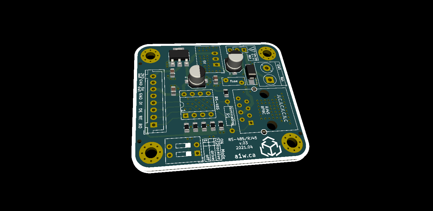
In this iteration, I liberally added thermal vias under every component which could potentially get hot with 2~3A of current going through it. I also added more silkscreen labels to clearly identify things, and switched from 6-pin to 8-pin JST header. This adds an extra GND pin to make it easier to wire 5V to one device, and 3.3V to another device. I also decided to break out the DE pin so it's possible to control that pin through an MCU as well.
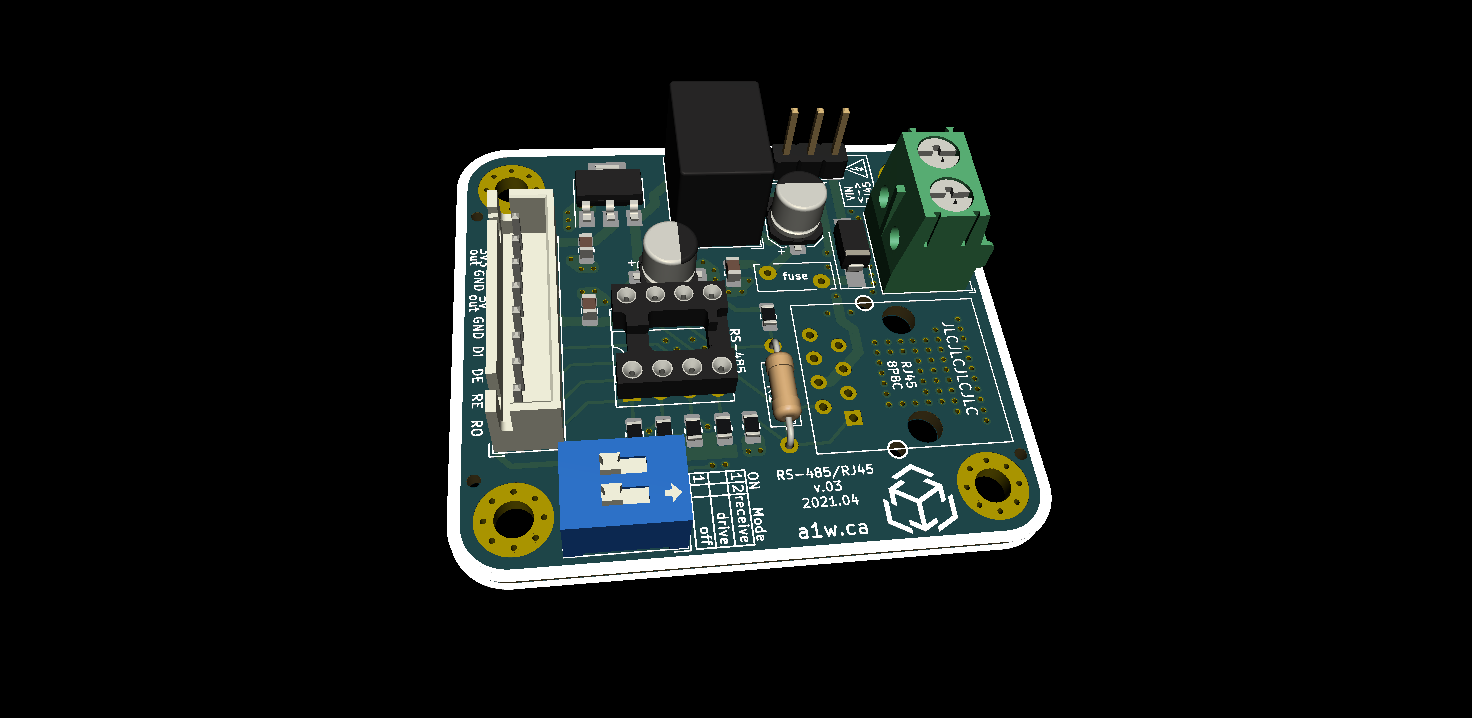
The DIP switch allows for manual configuration of the RS485
operating mode (receiver/driver/off), and there's a 3-pin header which
can connect VIN to RJ45. I initially wanted to use a high-current rocker
switch, but it adds a lot of bulk and cost to the module, so I opted
for a riskier 3-pin header with scary warning labels.
The important thing is to avoid touching those headers while the board is powered. That's common sense, but hey...
Anyways, since this is more of a development/hacker board, people are free to wire things as they wish (ex: skip soldering the 3-pin header, use an 8-pin header instead of the JST connector, etc).
The 3.3V LDO was initially user-selectable, but I decided to opt for an SMD SOT-223 LDO which is limited to 1A but should be fine for powering a small MCU like an Arduino Pro Mini.
For now I'll keep waiting for v.02 before making further changes to v.03.
Discussions
Become a Hackaday.io Member
Create an account to leave a comment. Already have an account? Log In.