Alexander Williams
-
Version update coming: new project
06/30/2022 at 23:41 • 0 commentsI've designed and built a new model of this board, except it's a bit different and has a completely different layout and PCB board size.
For that reason, I'll be publishing it under a new project, and the best part is it works perfectly with this board.
This board will also receive a revision (v.04) with more SMD components.
More details in August, as I wait for, and test the first prototype.
Stay tuned...
PS: Here's a hint - μHAT ;)
-
Available on Tindie!
08/03/2021 at 23:06 • 0 commentsIt took a while, but I finally put the modules up for sale on Tindie!
I'll publish the wiring diagram and soldering instructions within the next few days.
-
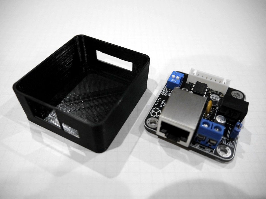
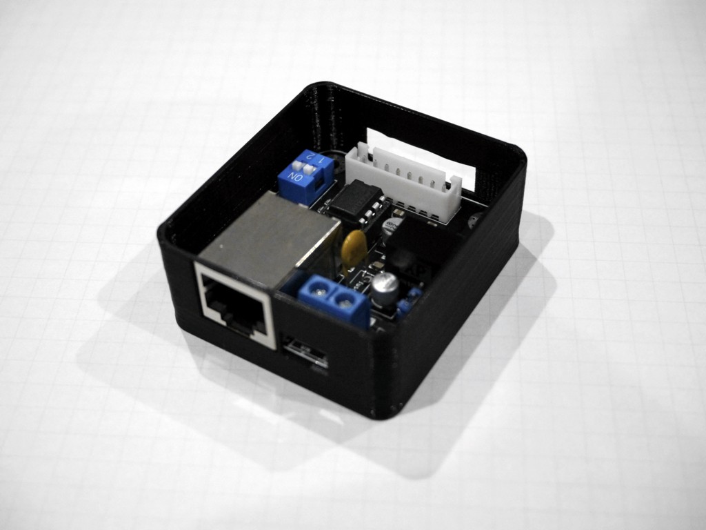
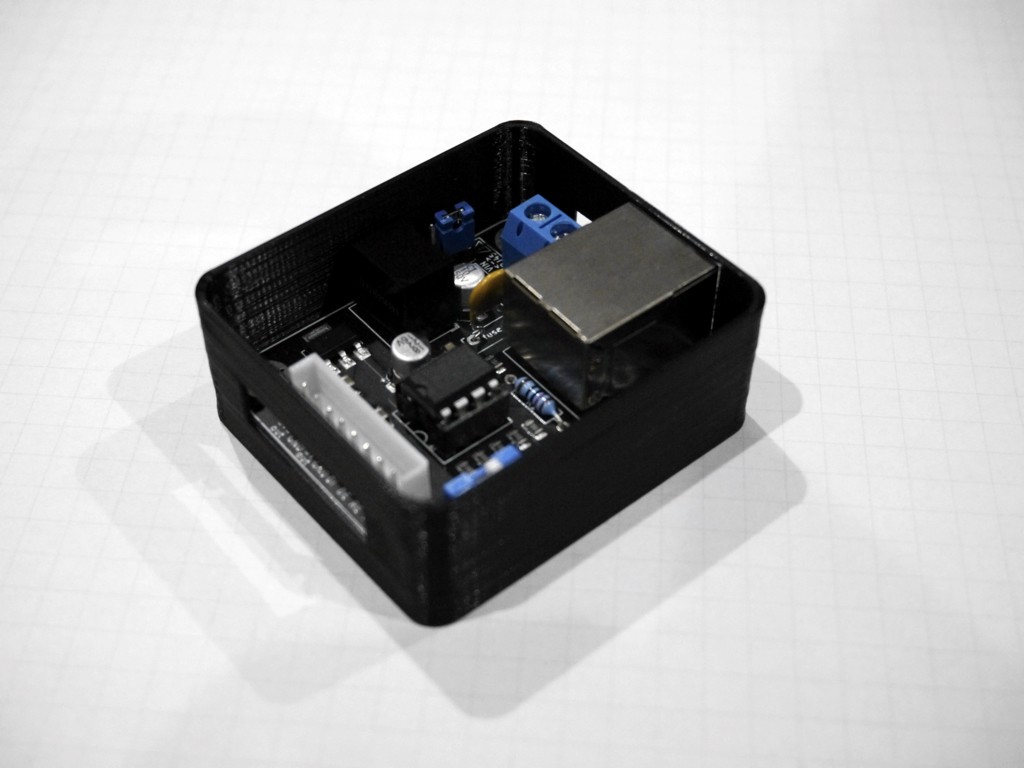
A box for this module
06/14/2021 at 08:59 • 0 commentsI spent a few days designing a stackable box for the module. I've finally successfully 3D printed a prototype of the bottom part (still missing the top/cover for stacking), here are some photos:
![]()
![]()
![]()
It's a bit underwhelming, so i'll keep iterating on this until it looks awesome. -
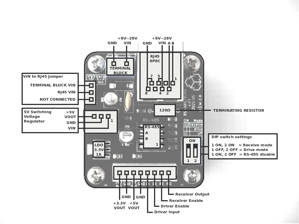
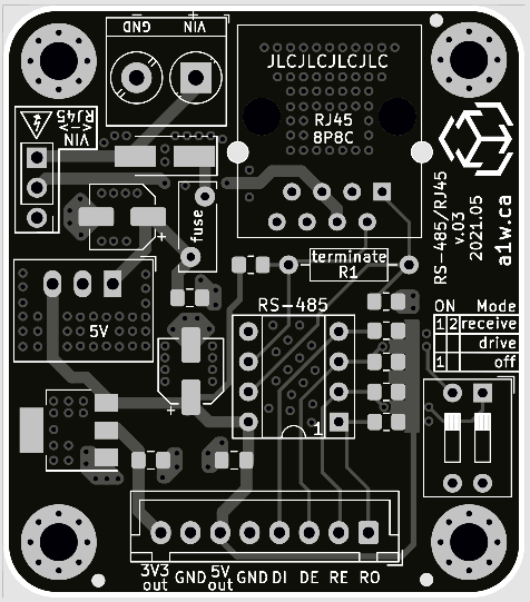
A pinout for module v.03
05/22/2021 at 03:19 • 0 commentsI made a pinout for the v.03 module and thought I'd share it here. It'll be part of the documentation which I'll publish hopefully within the next week.
![]()
-
Initial tests with v.03: success!!
05/18/2021 at 05:30 • 0 commentsI soldered the components onto two v.03 modules and ran some initial tests with a string of 5V LEDs, so far the modules work perfectly!
"Off" mode, set through the DIP switches also works as designed.
I'll continue some load and noise tests, and post another update once that's done.
-
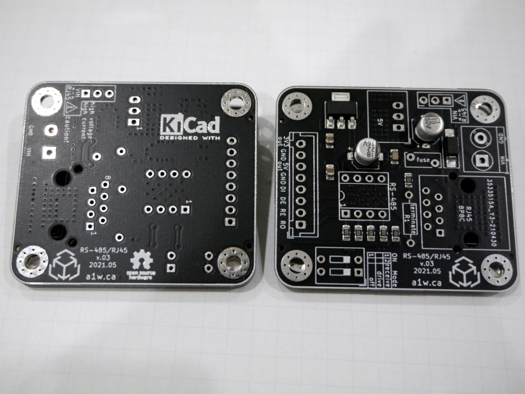
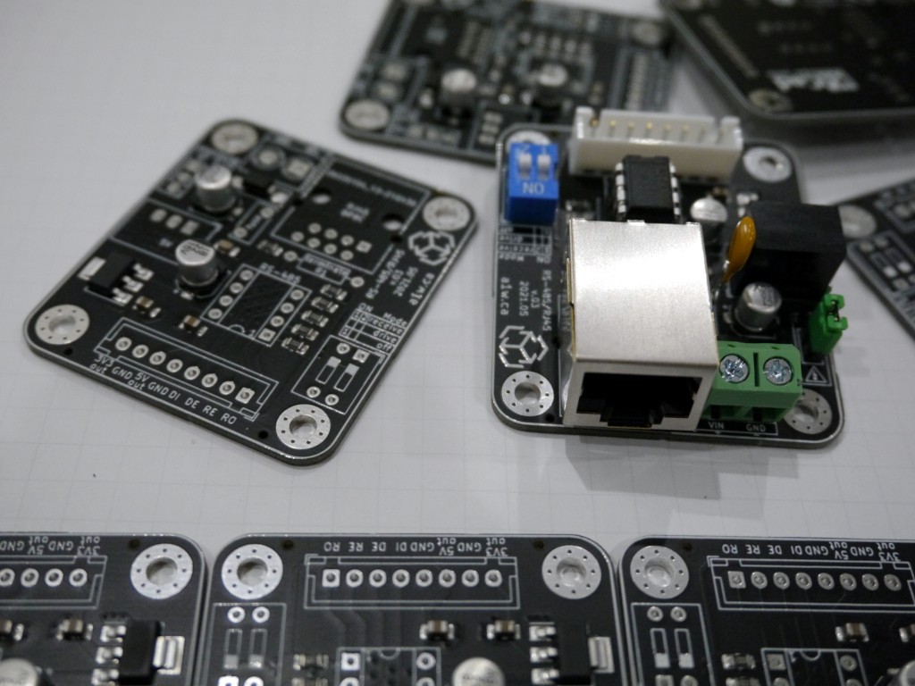
Yay, v.03 boards have arrived
05/17/2021 at 09:20 • 0 commentsIt took a few weeks, but the new boards are finally here!
![]()
I tried adding thermal vias throughout the board, but it seems the soldermask covered them. I'm not sure if that's better than leaving the vias open, but my guess is it'll at least prevent solder from the through-hole components from being wicked through the board.
The first order of business is to solder the through-hole components, run some tests and ensure they work as designed.
![]()
If all goes well, I'll put the kits up for sale on Tindie.
Afterwards i'll (finally) upload schematics and gerbers etc to GitHub.
-
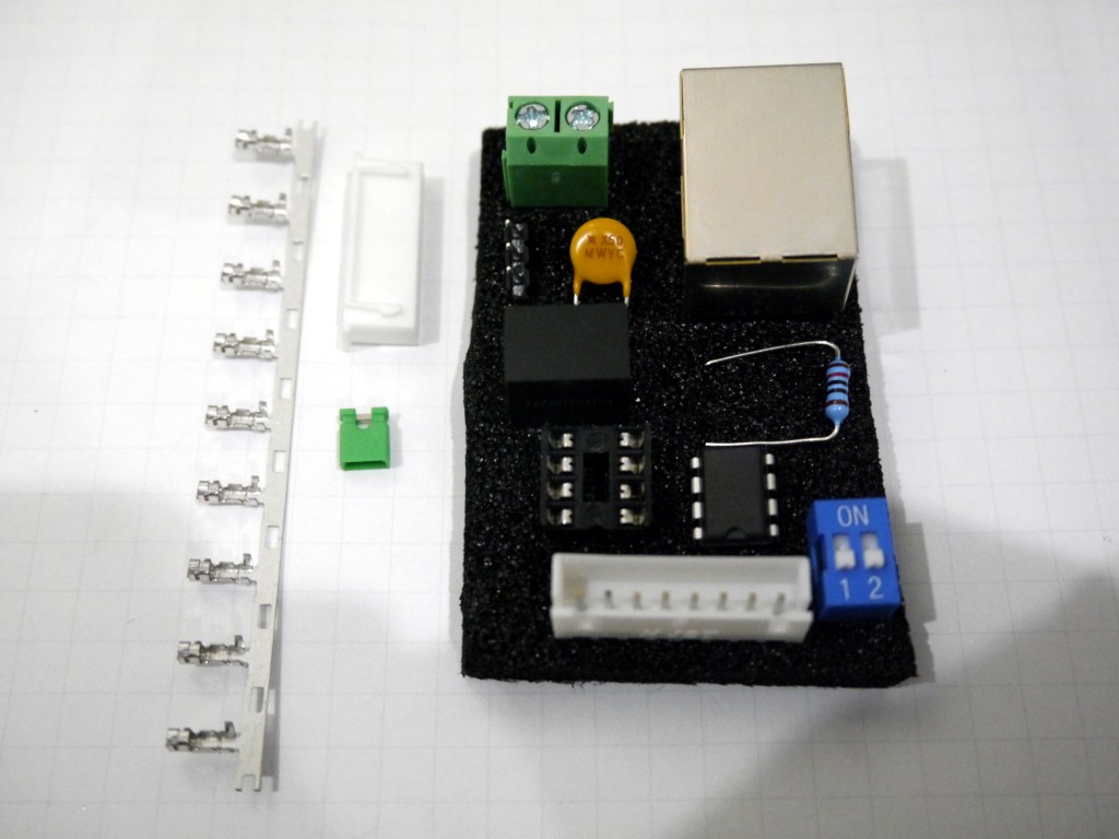
Kit components for v.03
05/03/2021 at 01:41 • 0 commentsHere are all the components included with the v.03 kit (without the board):
![]()
In total there's exactly 40 solder points, and there's a recommended order for soldering the parts which I'll explain in the provided documentation.The 120ohm resistor is optional, depending on the setup of you modules/system. The 3-pin 2.54mm male headers, DIP switch, 8-pin JST-XH header, and 2-pin screw terminal are also optional depending on how you want to connect/use the module. The fuse is rated at 500mA (trip 1A) and can be swapped for a larger fuse if more current will be drawn. The 5V switching regulator is rated at 1A and can also be swapped for a larger one. Finally, the RS-485 transceiver (MAX3088) can be replaced with another one that's pin compatible (ex: MAX3085) but check the datasheets to ensure the pinout is the same.
![]()
I can expect to put the board and kit up for sale on Tindie within the next 3 weeks - assuming all goes well with the v.03 boards. -
Initial tests with v.02: success!!
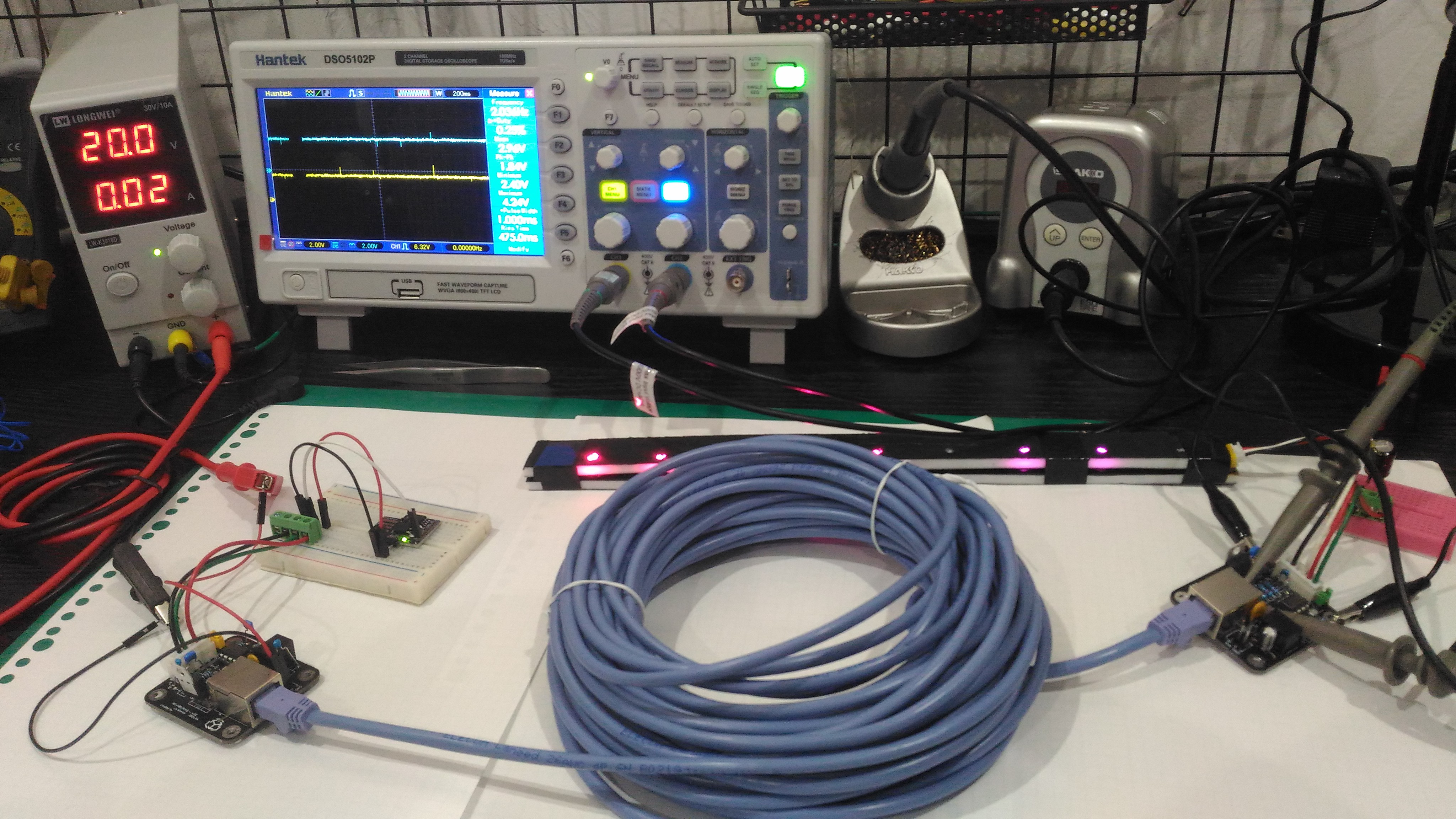
04/30/2021 at 04:39 • 0 commentsI ran a battery of tests on two v.02 modules (soldered) and everything works perfectly!
![]()
I made two modules, one with electrolytic capacitors, and another with ceramic (ceramics were part of the v.02 design, electrolytic was just a random idea I wanted to test).From the photo above, you can see the two modules connected through a 15m AWG26 RJ45 cable, and the left module is powered directly by 20V.
![]()
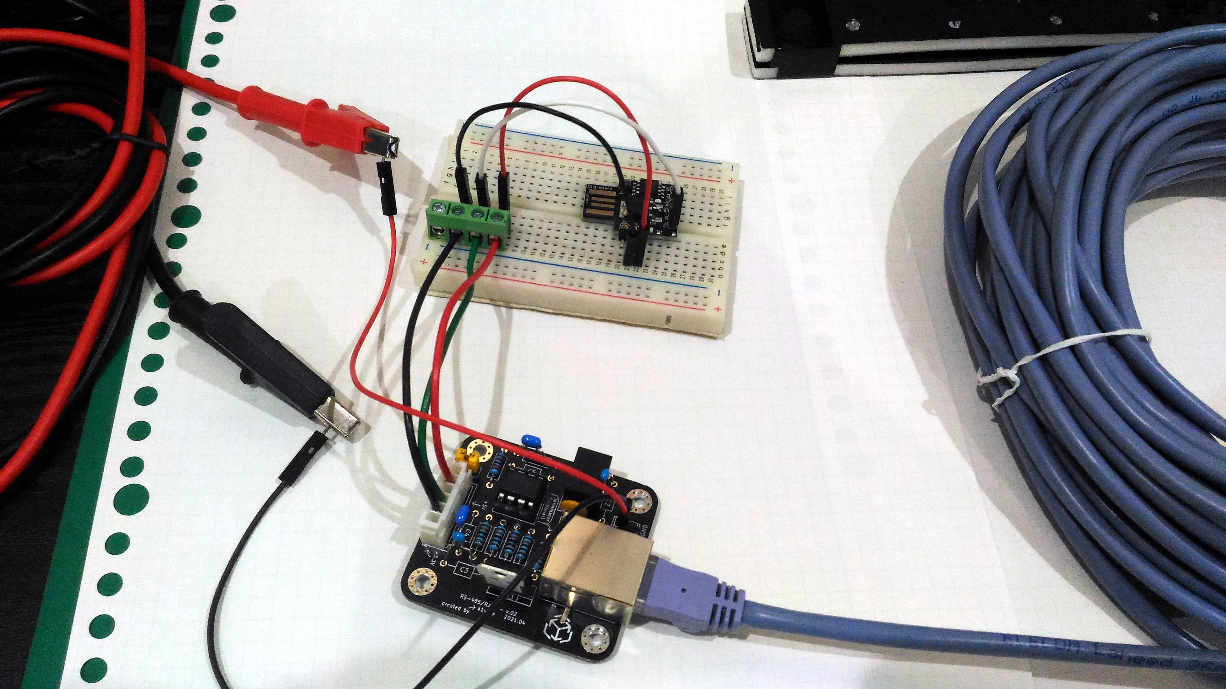
Here you can see the left module connections. It is powering a clone DigiSpark with an ATtiny85, with 5V, which is programmed with the Adafruit Neopixel srandtest example program configured for 9 LEDs. The connector only needs 3 wires: 5V, GND, signal (DI). Since RE is pulled high by default, the DigiSpark is set to "Drive" mode so I didn't need to wire the RE pin.
![]()
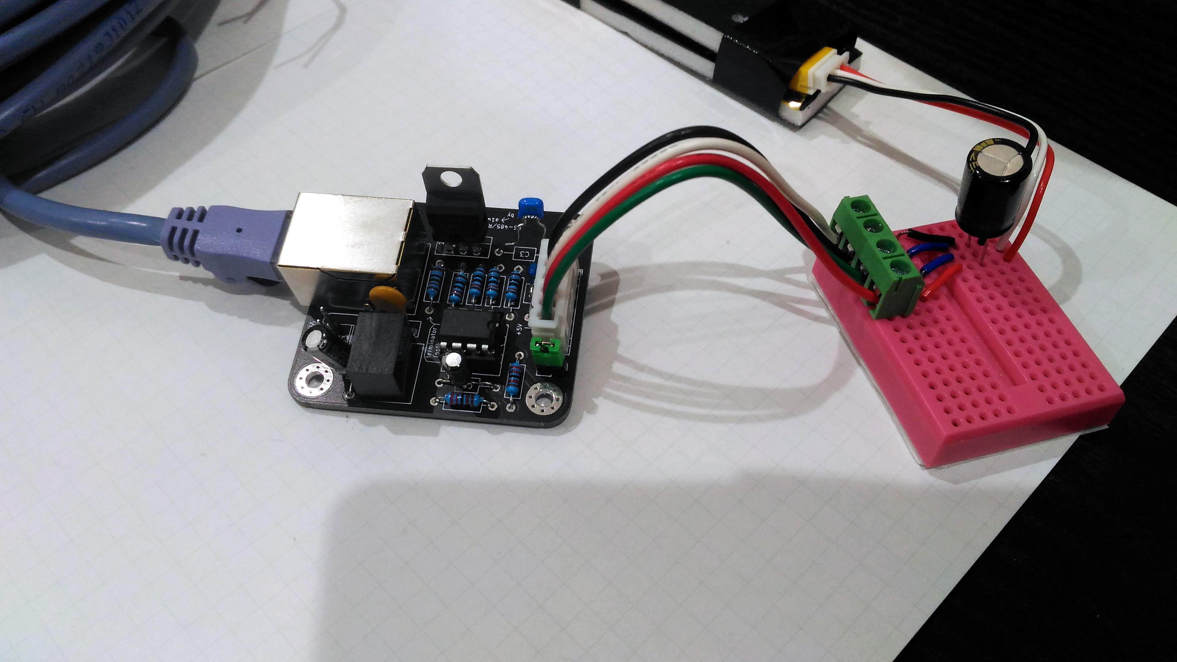
Here we have the right module connections. It is powering a small strip of nine WS2812 LEDs. In this case the connector has 4 wires: 5V, GND, signal (RO), and RE, and I use a tiny breadboard to tie RE to GND - thus setting it in "Receive" mode.
The v.03 module has a nice feature that lets us tie RE/DE to ground or high through simple DIP switches. We'll also be free to set the operating mode manually, or wire everything to the MCU and set them through code.
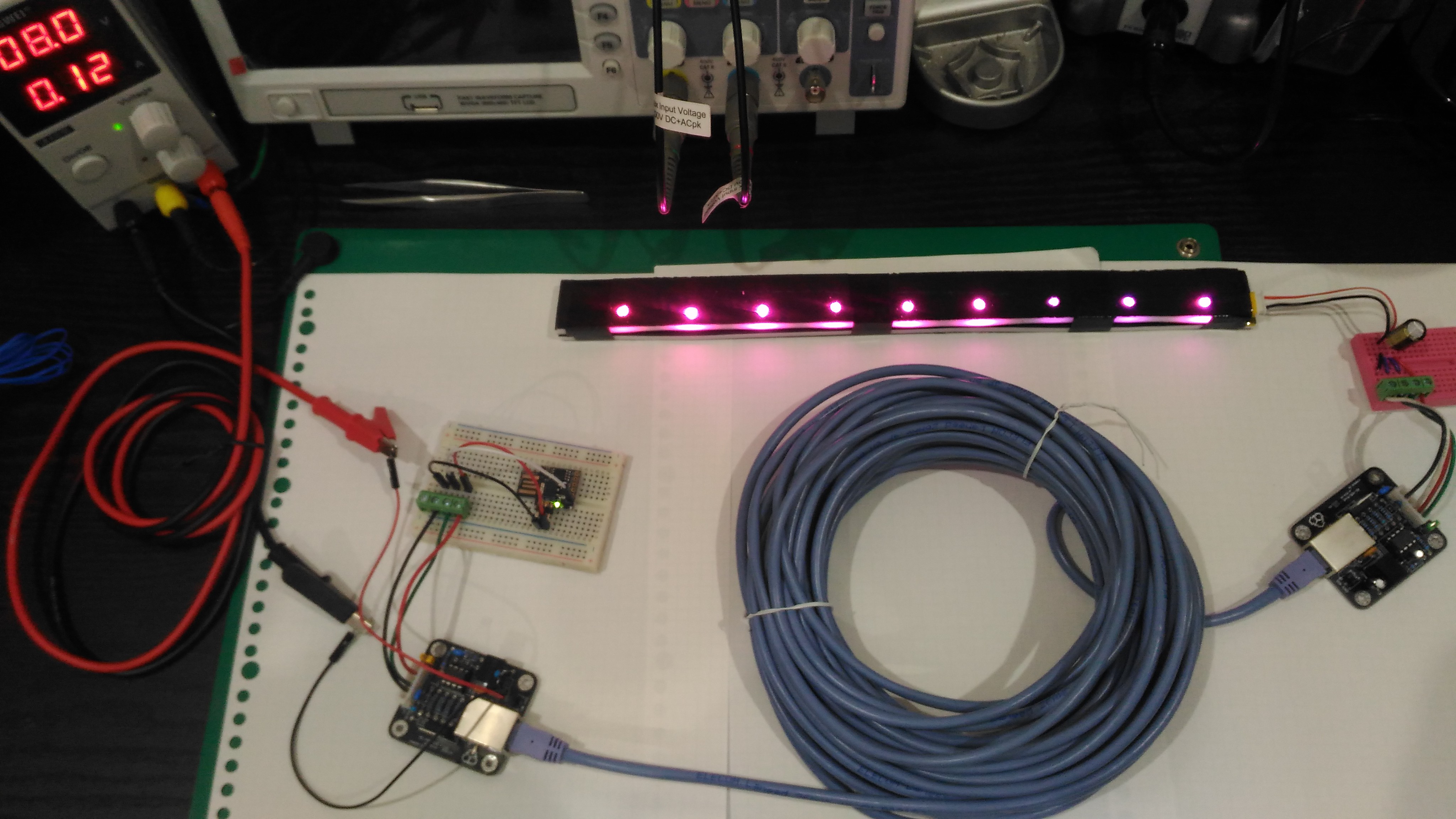
![]()
It works at minimum 8V too, however the LEDs pull significantly more current at that voltage. I did check the temperature of the switching regulators with a type K thermocouple, and it didn't seem to go over 28deg C. Although that's hardly conclusive considering the low current being drawn.
I did notice a lot of noise on the A/B input pairs at R1 on the right module (receiver), but that's due to the lack of low frequency bypass capacitors. The electrolytics alone are insufficient (they weren't even part of the v.02 design either). The v.03 module has a mix of ceramic and electrolytic at the inputs and output, so there hopefully won't be too much noise there.
I'll make a few minor changes to the v.03 design, and send it to the fab over the weekend. While I wait for those, I'll get to work on documentation for those who want to DIY and/or buy my kit.
-
Why not PoE?
04/29/2021 at 23:12 • 0 commentsAn obvious question is "why not just use Power-over-Ethernet?"
Well, technically this module is essentially a passive PoE device following the 802.3af mode B pinout, but without adhering strictly to the spec.
When looking at passive PoE devices, you'll typically find something like this:
![]()
The problem with these cables is they only work with devices which are already networked, such as IP cameras and phones. Moreover, if the devices don't support the voltage received from the injector, they could easily be damaged.In the situation where you want to control some 5V LEDs from a long distance using a wired setup, you'll need a DC-DC converter and an RJ-45 connector at the LED end, and you'll also need an RJ-45 connector near the MCU. Finally, you'll need some kind of device to send your data signal as a differential signal, assuming you want it to arrive intact at the destination - that's where the RS-485 transceiver comes into play.
In the end, a DIY setup to support "PoE" with non-networked devices will end up looking exactly like this module.
Note: I didn't discuss "Active PoE" because that involves a bit more hardware and a lot more complexity.
10mbps over 1km on a single pair of wires
A simple 46mmx22.5mm module to route power and differential signals (RS-485) over RJ-45