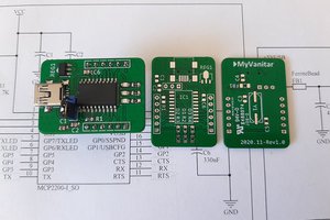
In the past I used Silicon Labs UART bridges but had bad time with them. For some time I wanted to try FTDI chips. This module is based around FT231XS UART bridge. Cool things about FT231:
- Available in SSOP (reliable to solder) and QFN (small) packages.
- Full handshake UART (RX, TX, RTS, DTR...).
- FT_PROG tool to set custom parameters in device EEPROM (Device name, Serial number, Current limit, Invert logic state of pins...)
- Configurable CBUS pins (CLKOUT, PWREN, SLEEP, TX/RX LEDS, BATTERY DETECT...).
For USB Type C connector I picked one manufactured by Hirose. In the past I had bad experiences with cheap connecters that would go loose after few hundred insertions. Plan is to test this one to see if I can use it on future projects.
Schematic is textbook implementation of all above mentioned components.
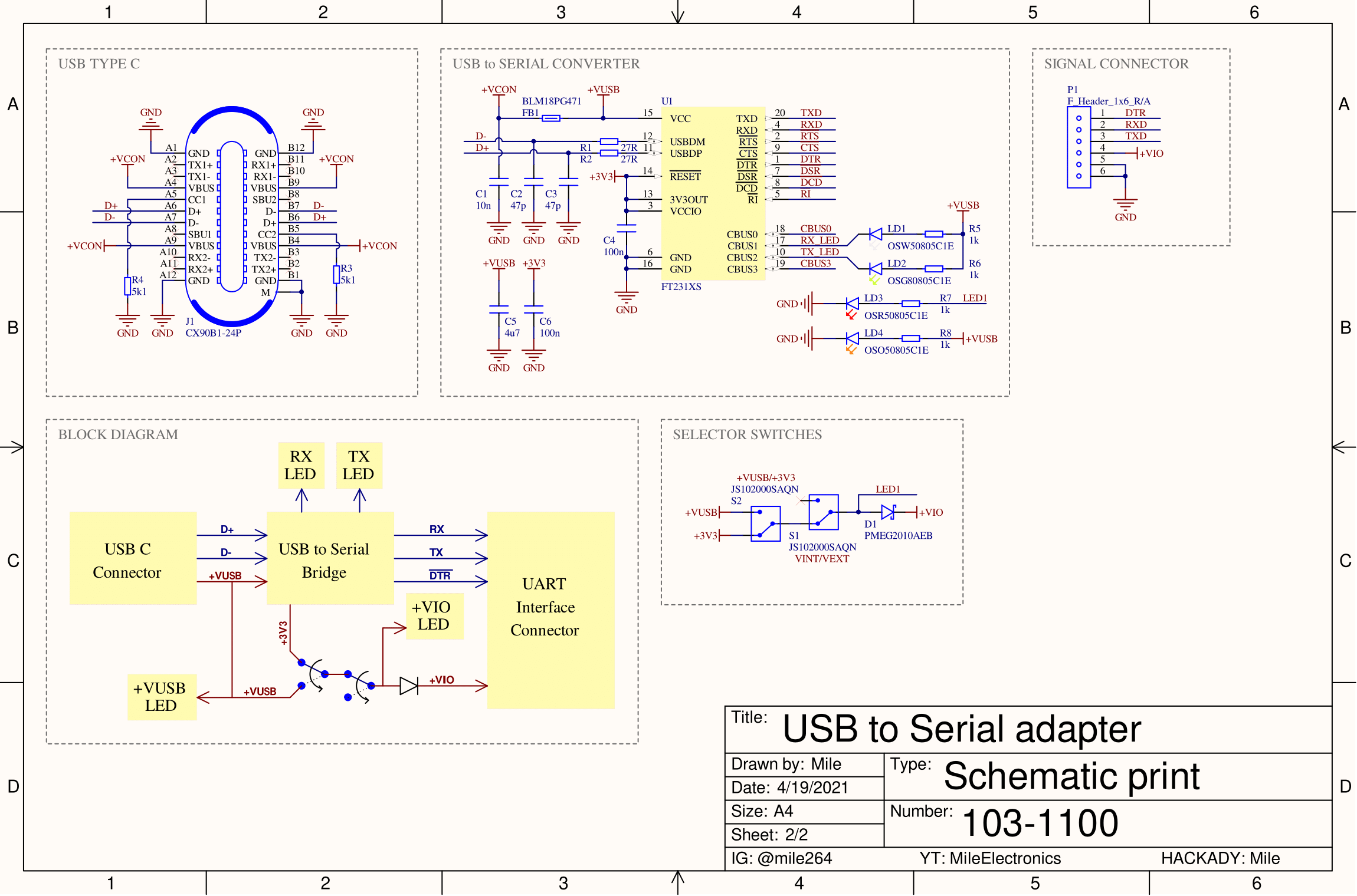
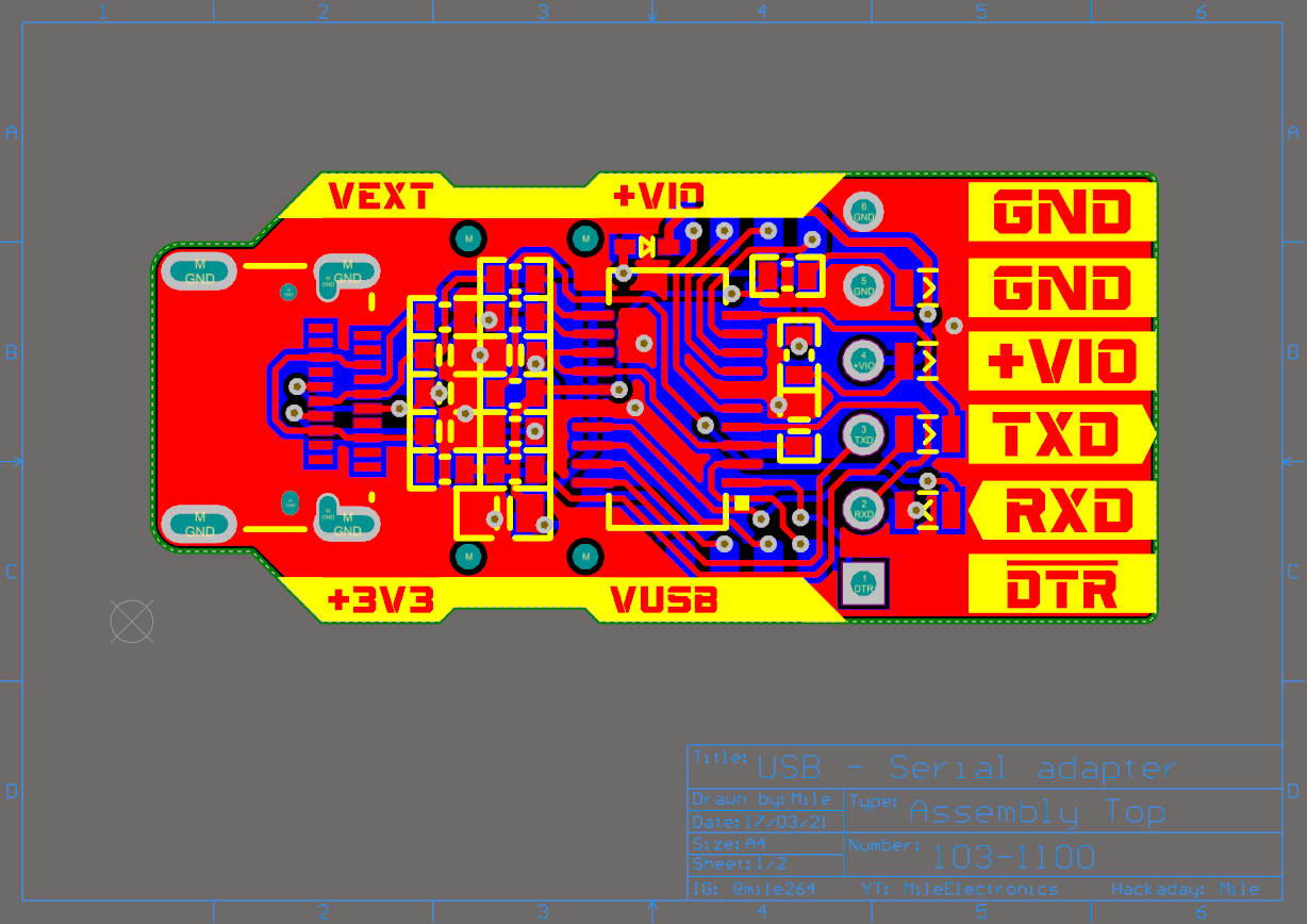
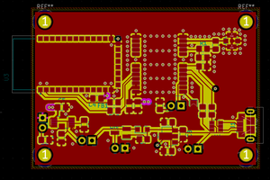
PCB is designed so that is easy to manufacture and assemble. That means that clearances and trace width are 0.2mm and all passives are standard 0603 size. Here is TOP PCB print.
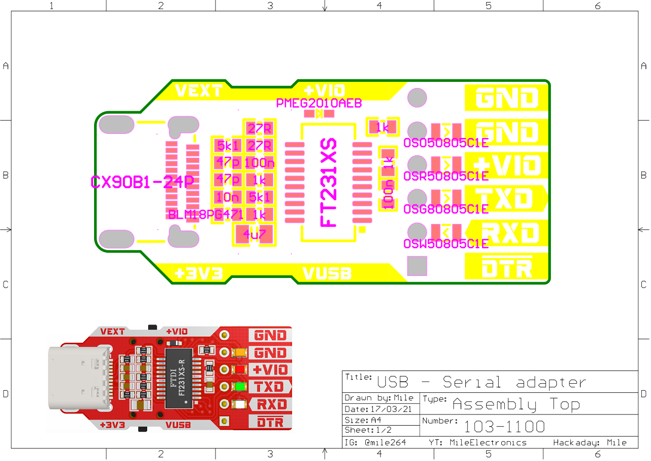
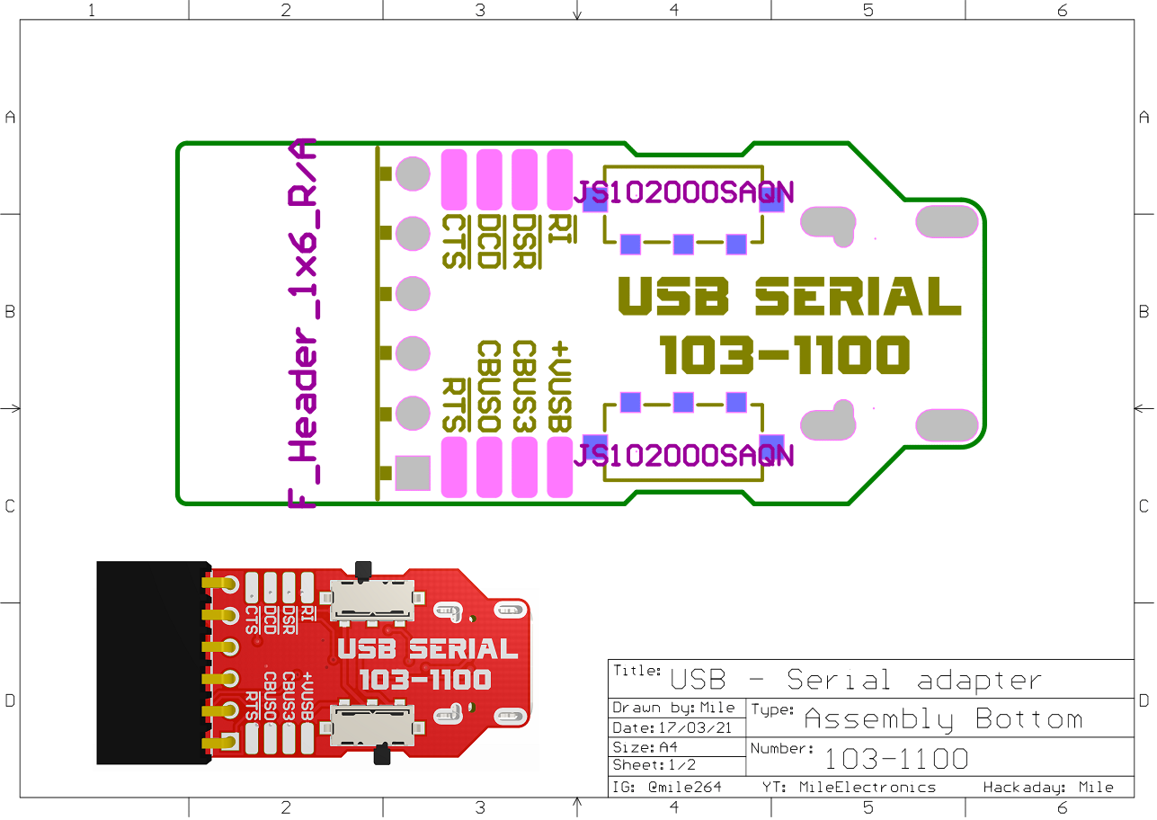
For PCB assembly you can follow this assembly drawings:
 Mile
Mile
 hesam.moshiri
 Bharbour
Do you mind providing the files? I'd like to learn from your project. Thank you very much.