How to develop the programming logic and the operation of several sensors? Several people have great difficulties in developing projects because they do not develop this knowledge.
The biggest problem with this is that they miss opportunities to develop projects, lose customers, and are prevented from learning other things because they cannot evolve. In addition to all this, we have great frustrations and, many times, we think about giving up our learning.
One of the ways to solve this problem is to use didactic and ludic resources, so that we can learn these concepts more easily.
Among the various features, we highlight the Arduino elevator.
This Arduino elevator consists of the following electronic elements:
- 4 x reed switch sensor modules
- 1 x LCD Display
- 1 x DC motor
- 1 x Driver for DC Motor
- 1 x Arduino UNO
The Arduino elevator structure was developed to support the sensor modules on its side. They will emit a signal when they detect the position of the Arduino elevator through a neodymium magnet.
How does the elevator work?
In this project, the Arduino will be responsible for activating the elevator motor driver, controlled according to the desired floor by the buttons.
Each button installed in the structure corresponds to the desired floor, which when pressed, the engine will run until the destination is reached.
In this article, you will understand the assembly of the didactic elevator, as well as know its mechanical structure, which was fixed only by means of fittings, and if necessary, the use of glue to fix the structure is indicated.
What will you learn in this project?
- To understand the structure of the Arduino elevator using the sensor reed switch module, the LCD Display, the DC motor, as well as its drive and the Arduino UNO;
- Analyzing the fixation of the mechanical structure of the Arduino elevator case; Didactic through its inserts;
- To know the importance of each part of the Arduino elevator structure for the project as a whole;
- How to develop the operating logic of the Arduino elevator.
Now, we will begin the complete presentation of the development of the Arduino elevator.
Let's learn how to make the Arduino elevator?
Are you curious to learn and make your elevator with Arduino? We will explain in detail the complete project of this elevator.
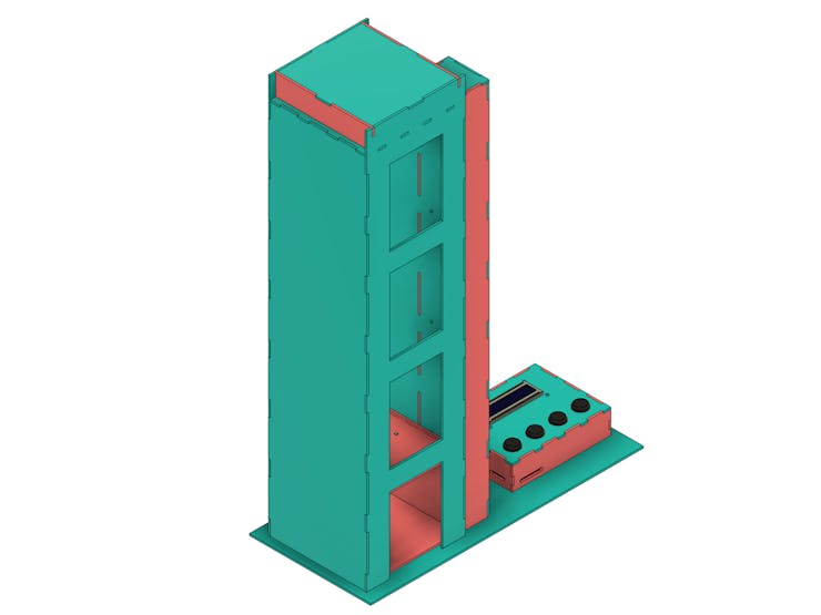
The elevator of this project is formed by several sensor modules and other electronic devices and its physical structure is the same as a 4-story elevator.
In addition, the entire structure has electronic components that guarantee the functioning of the elevator. Figure 2 illustrates the internal Arduino elevator region.

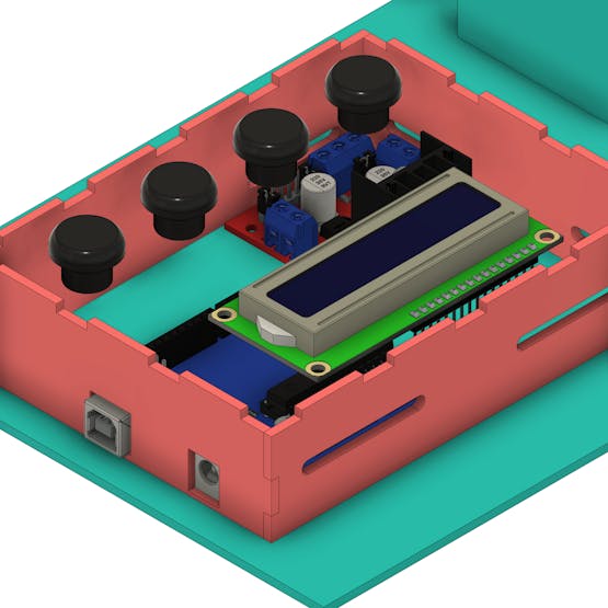
In its internal structure, it is possible to observe the 4 reed switch sensor modules, the DC motor. The other electronic elements in the control box structure, such as the buttons, the LCD, the motor driver, and the Arduino UNO.
The entire structure of the elevator was developed through finger-type fittings so that we can fix the parts with glue.
Figure 3 illustrates the fitting surfaces of the Arduino elevator control case.
In addition to the Arduino UNO, we provide an Arduino for you to download and assemble your project. You just won this Arduino!
Use the JLCPCB Arduino Compatible printed circuit board presented below.

You can obtain the Arduino JLCPCB compatible PCB for your projects for $2 in your first order with the link: Earn my PCBs Arduino Compatible.
Use the JLC-RECE coupon,earn a $2 off discount, and earn FREE5 PCBs.In addition have other discount coupon with $18 discount for your other projects.
Now, see how the project's control structure works.
How does the control structure work?
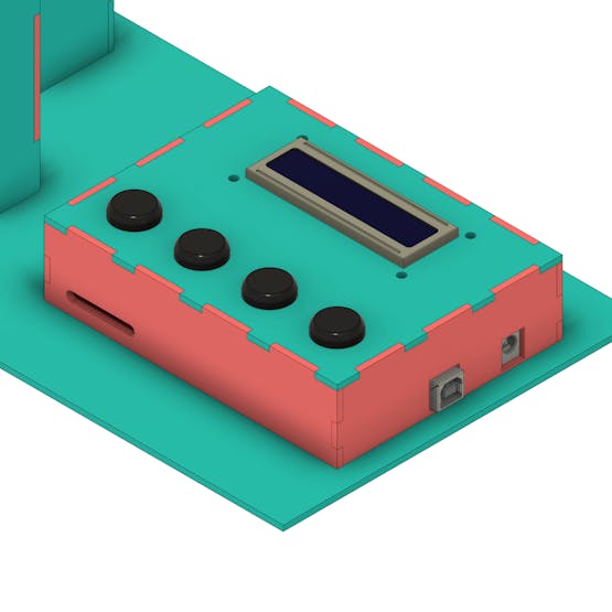
The control case was modeled with some slits on the side, in order to facilitate the connection of the sensors and motors wires. The slots are shown in the figure below.
This case has a total of 4 buttons, each of which corresponds to a specific floor of the Arduino elevator.
You must press the button for the desired floor and the Arduino will send the command to the L298N driver, which is able to control the speed and direction of rotation of the elevator motor.
In addition to starting the DC motor, the Arduino will monitor the reed switch sensors and check the movement of the cabin to the desired floor

The cabin will go up or down based on the selected deck. The movement of the cabin and other information will be shown on the LCD.

When starting the engine, which is connected to the pulley structure, the cabin will go up or down.
Figure 9 illustrates the arrangement of the DC motor in the upper region of the Arduino elevator. See the figure presented below.

These are the main points that make up the working structure of our Arduino elevator.
Now, we will see how to create the algorithm for controlling the structure of the Arduino elevator.
How does the algorithm logic work?
The system starts by presenting the initial position of the cabin on floor 0 and waiting for user requests.
The user must press the button for the desired floor and then the Arduino performs the reading and selects the direction of rotation for clockwise (up) and counterclockwise (down).
After that, the Arduino reads the sensors to verify that the cabin has reached the desired position.
In the cabin, there will be a neodymium magnet to activate the sensors based on their position.
The Arduino deactivates the engine when the cabin reaches the desired floor. After that, the system updates the position information on the LCD and waits for a new request.
You can use this algorithm structure to start building your elevator. In addition to it, you can make several other modifications to the programming logic for this project.
Acknowledgment
We thank Ludic Robot School and the company JLCPCB for offer support to create this project.
Use the JLCPCB Arduino Compatible printed circuit board presented below.

You can obtain the Arduino JLCPCB compatible PCB for your projects for $2 in your first order with the link: Earn my PCBs Arduino Compatible.
Use the JLC-RECE coupon,earn a $2 off discount, and earn FREE5 PCBs.