This project was developed in partnership with Robô Lúdico School and JLCPCB Factory that offers 5 free PCBs of Arduino Compatible Board.
Your robot with wheels will not work on some terrains! Read on to understand this problem and how to resolve it. Most mobile robots are built with wheels.
See the robot with wheels presented below.
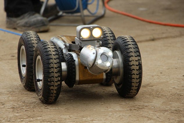
They are great for navigation on flat terrain and with few irregularities, but present great difficulties for operations on terrain with high irregularity.
Why does this defect happen with robot with wheels, and what are its consequences?
This is because the wheels lock or slide on the surface of the terrain. This prevents the robot from moving and arriving at its destination.
In addition, the wheels cannot overcome large obstacles on the ground. For this, the robot with wheels would need to be twice the size of the obstacle and this would make the wheel structure unfeasible to be built.
To solve this situation, it is ideal to use a track robot.
In this article you will learn:
- Build a robot capable of moving around different types of terrain (here I will show you how to increase your robot's mobility for any type of terrain)
- How the structure of a track works
- How to obtain the control board of the treadmill robot
- The reasons that guarantee the superiority of the structure of the track robot in relation to a robot with wheels.
See an example of a track robot.
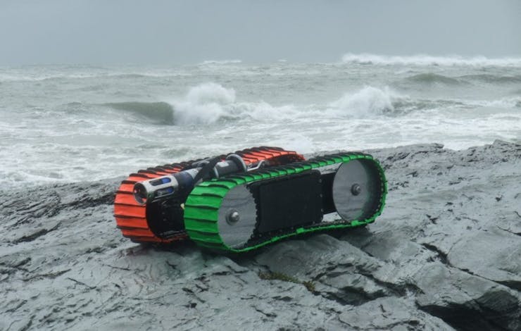
Mobile robots with wheels are the best tools when we want to carry objects and explore environments that pose risks to human life. However, these terrains cannot be uneven, as this prevents the mobility of the robot with wheels.
For this case, I recommend that you use a track robot because the treadmill offers greater traction and reduces slippage.
The tracks offer a better way of getting around to travel in rough, uneven, and loose terrain and pass through various obstacles.
Now, you will learn how to build a mobile robot with a track, and we will talk about its main advantages and disadvantages in relation to the robot with wheels.
Now, we'll learn all points presented above.
What is a track robot?
These robots use treadmills instead of wheels and are widely used in rough, uneven, and loose terrain. The treadmills allow the robot to pass through several obstacles because it has a larger area of contact with the ground and offers greater traction to the robot.
How tracks are constructed?
The project was built in the shape of a tank and its internal structure has all the electronic components that will process the signal and perform the displacement of the robot.
Figure 2 illustrates the robot's internal region.
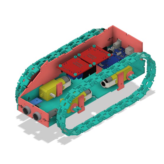
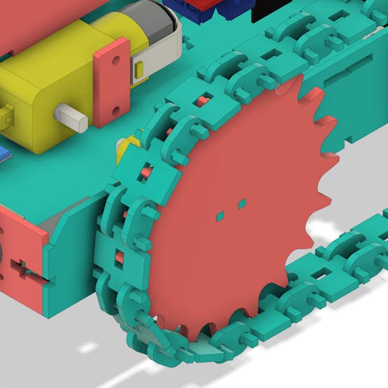
In its lower internal structure, it is possible to observe the 4 motors (each with two lateral supports) and their respective sprockets, as well as the two line-following sensors.
The DC motors and driver
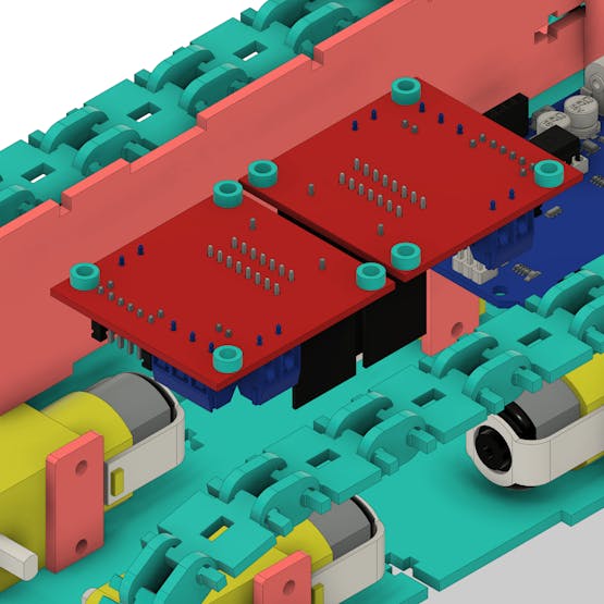
The robot consists of 4 motors and two drive drivers. See the figure below.
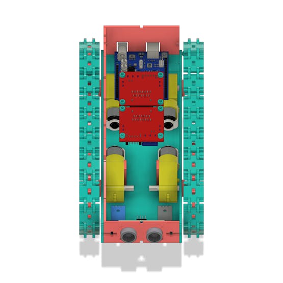
The drivers are responsible for receiving the command signals from the Arduino and activating / deactivating the motors. For each pair of engines we will use an L293D driver.
This driver can control from the speed of the robot's sprockets through the PWM pins of the Arduino, to the direction of rotation, being able to control up to two DC motors.
The drivers were installed on the inner ceiling surface, next to the Arduino Uno.
The motors are coupled to a sprocket. It is responsible for transmitting the movement to the conveyor, which is attached to its structure.
The structure of the track is shown below. It was built from the coupling of several parts.
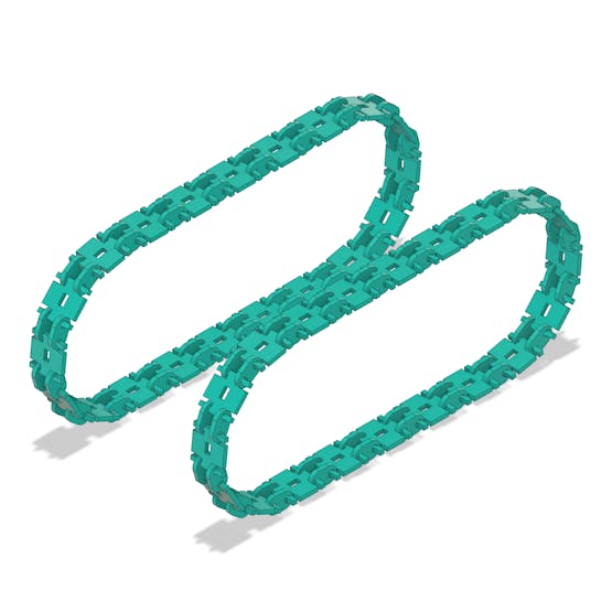
This structure is basically divided into two categories: the link and the wheel connection. The connection is responsible for connecting the cogwheel, and they unite them.
Figure 5 illustrates the mechanism of the links, connections, and sprocket. The connections are responsible for engaging the teeth of the wheels, thus allowing the engine, when turning the wheel, to displace this mechanism.
The links are responsible for joining each connection to others, allowing the displacement of the system to be possible.
Each link and connection was modeled in order to fit “justly” in order to ensure the maximum stability of the mechanism. Along with the links and connections, the sprockets are the means used by the tank for its displacement.
The track moves according to the activation of the motor control circuit.
How does the motor drive control work?
See now in the next topic.
The control board of the track robot
The control board is shown below and has the Arduino UNO format. All sensors and drive drivers will be connected in their structure.
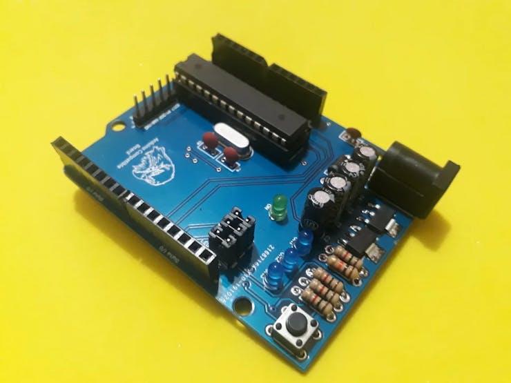
The control board is responsible for receiving control commands via Bluetooth or sensors. Based on the information received, it will activate the drivers so that the motors can move the robot in a certain direction.
Did you win the files on that board? Follow this process and get 5 free units. It is easy to assemble!
You must follow all of these steps below.
- Download the robot control board file
- Enter in this website and make your account.
- Add the control board files to the website
- Add the JLC-REBE discount coupon to the payment section
- Ready, you won 5 free PCB units.
Now, see all the sensors that make up the robot's structure.
Sensors of the track robot
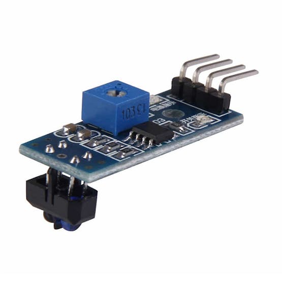
The track robot has 2 types of sensors in its structure. It has a reflective sensor and an ultrasonic sensor. See the figure presented below.
1 / 2
The robot has 2 TCRT5000 sensors and one ultrasonic sensor.
The TCRT5000 sensor is used to detect holes in the ground, follow lines and detect when the robot is on the ground working.
The ultrasonic sensor is used to allow the robot to avoid obstacles. The Arduino fires the sensor and waits for the received signal. From that time between firing and receiving it is possible to determine the distance between the Arduino and the target.
Now, we will see how to create the control logic for this project with the resources presented.
Programming logic for the operation of the robot
The robot structure can be used with different programming logic. The robot has internal space to install other modules and be controlled autonomously or remotely by commands via bluetooth, or wifi.
Use the programming logic below to control your track robot remotely with bluetooth commands.
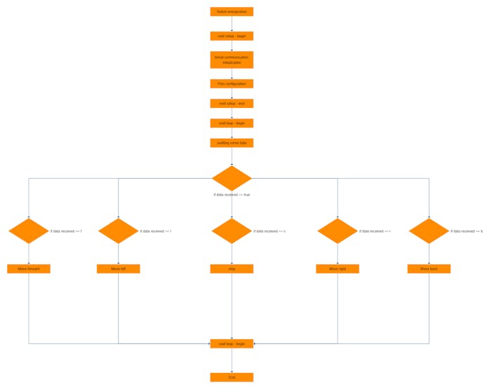
Implement this complete logic on the Arduino or the robot track control board. Get 5 free units of the board now!
Acknowledgment
We thank Ludic Robot School and the company JLCPCB for offer support to create this project.
Use the JLCPCB Arduino Compatible printed circuit board presented below.
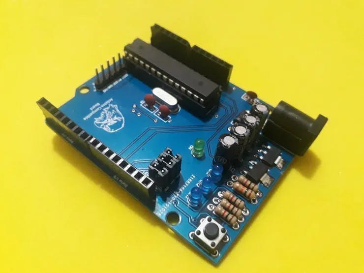
You can obtain the Arduino JLCPCB compatible PCB for your projects in your first order with the link: Earn my PCBs Arduino Compatible.
Use the JLC-RECE coupon, earn a $2 off discount, and earn FREE5 PCBs.