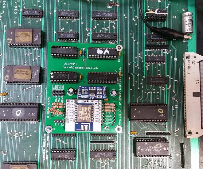
Over a year later and finally got around to dusting off the PCB's, populating with components and began testing.
Surprisingly, initial tests looked promising, but eventually hit a snag with GPIO0 pulled low at powerup which results in the ESP8266 booting into flash/program mode when the Galaga board was powered on.
Luckily a simple bodge swapping GPIO5 and GPIO0 with the relevant code changes resulted in a functional high score sniffer.
So basically, this project is completed!!! I can finally move on.
Next stage, tidy the code, install into a cabinet and see how it behaves in the wild.

Above GalagaIoT installed on the Video PCB. The bodge can be seen where GPIO0 and GPIO5 resistors were swapped.

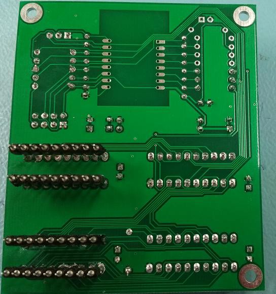
These extended pins were needed to facilitate plugging into RAM sockets 3E and 3F. A little fiddly and time consuming.
 justin.richards
Discussions
Become a Hackaday.io Member
Create an account to leave a comment. Already have an account? Log In.