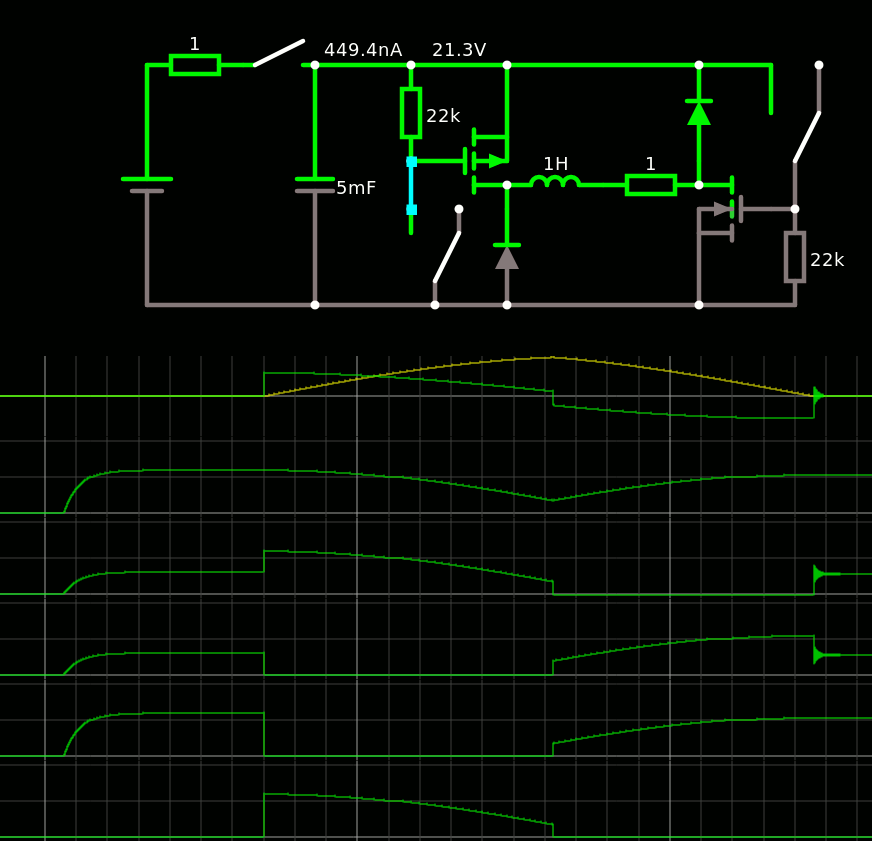
Of course, two diodes were useless.

The removed diodes might help protect the MOSFETs but the opposite diodes take that role, indirectly.
One cycle loses 3V, or 1/8 of the energy only. This reduces the heating of the coil and the time to recharge the capacitor. Energy savings are not the point, it was more to increase the pulse repeat rate while keeping dissipation low.
It doesn't matter if the MOSFET do not react immediately, as long it's shorter than 1ms. I have not used "MOSFET Driver" circuits here, adding capacitors will help simulate the effect of having a laaaaarge gate.
One big concern is to avoid the saturation of the core. This should be sensed when the current doesn't increase anymore. However the point of this system is to size the capacitor so the voltage decreases before reaching the limits of the coil.
I wonder if a L298-type bridge could work.
No, there would be too many power supply issues unless the cycle is shortened before the tank is empty.
And I aim at 10A currents.
 Yann Guidon / YGDES
Discussions
Become a Hackaday.io Member
Create an account to leave a comment. Already have an account? Log In.