 Afrdt
AfrdtAlthough my initial idea was to use two vibration motors - each one of them corresponding to the left and right probe, after doing some testing, I soon realized that the motors were drawing too much current from the circuit and they were creating background noise to the sonic output. So, I decided to bypass the right motor (as the circuit was already sewn, there was no room for adding extra components that could regulate it).
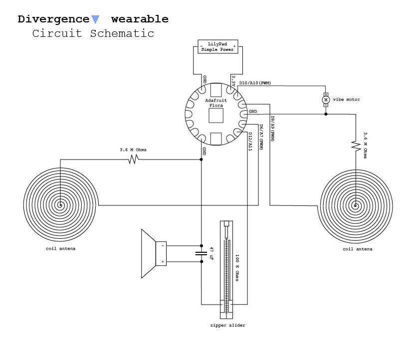
This is the final circuit schematic:
Discussions
Become a Hackaday.io Member
Create an account to leave a comment. Already have an account? Log In.