 brandon
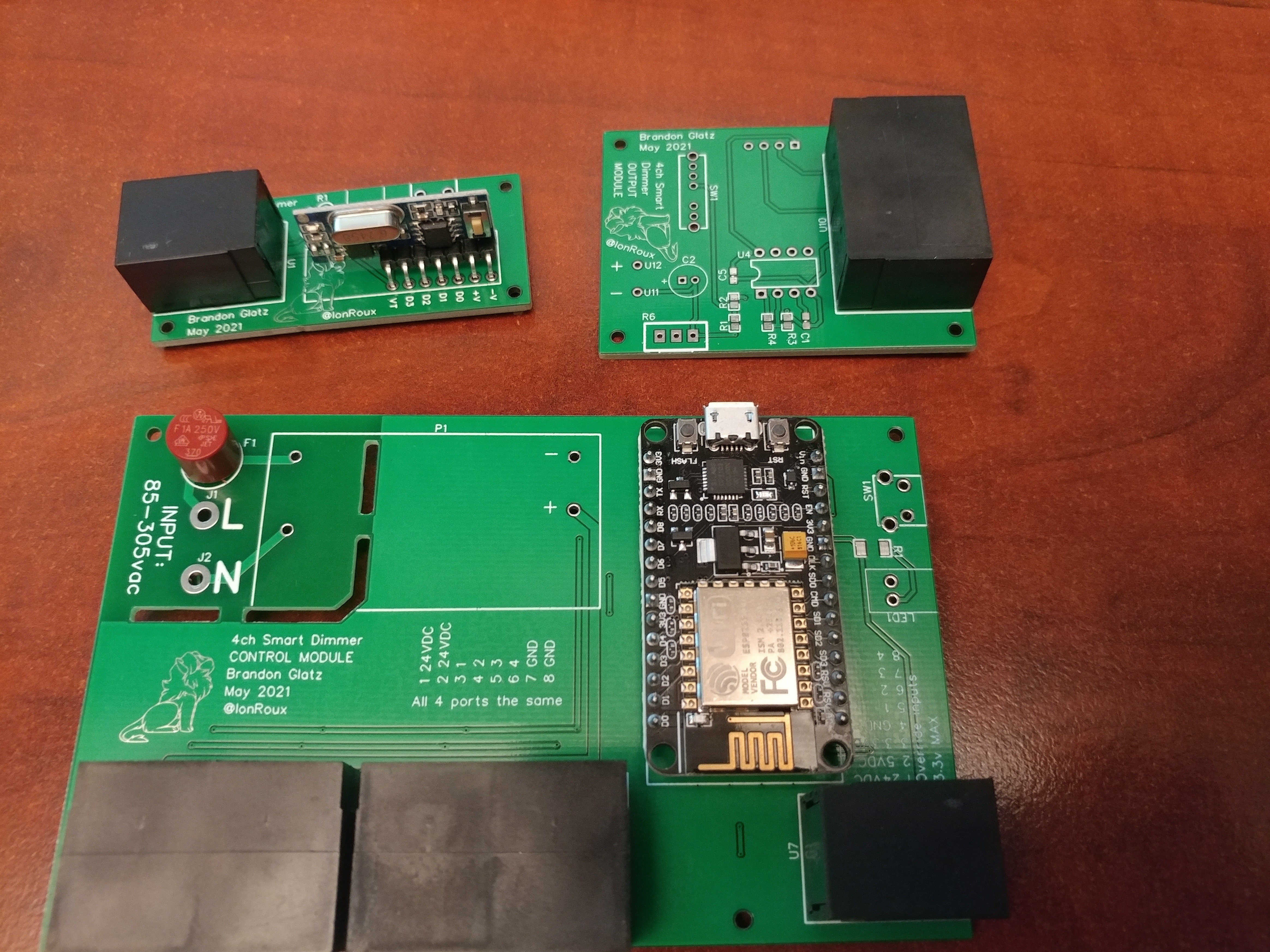
Boards look great. My fav part of order PCBs is discovering a problem within 5 minutes of opening the box.
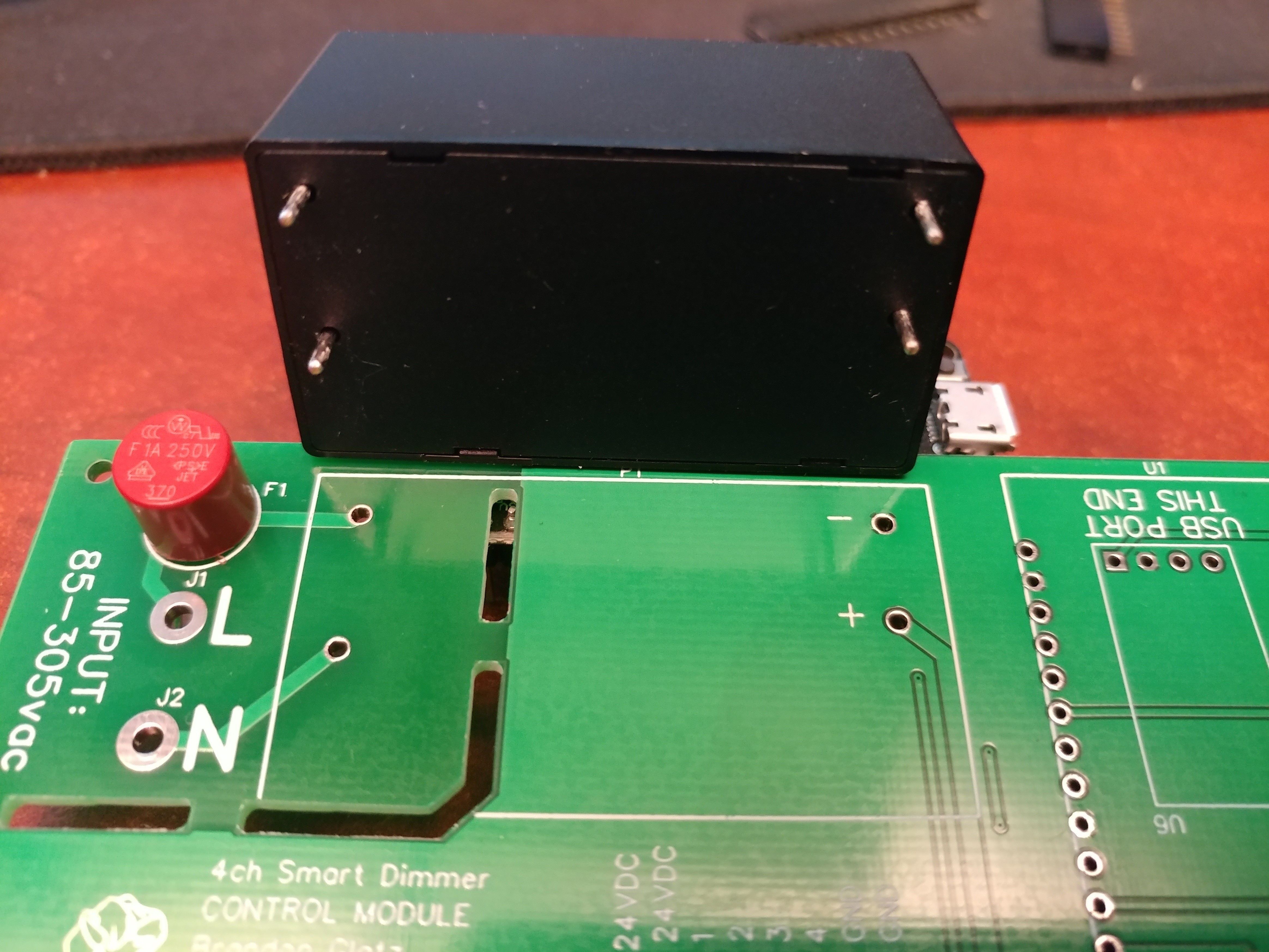
The holes for the 120v to 24v power supply don't line up. Consulting the datasheet I realized I missed something:
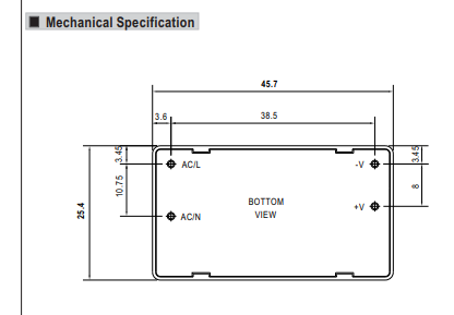
For whatever reason their hole layout is shown as if you are looking at the bottom of the component. Not top down on the board. I have never seen this before but I completely overlooked the bottom view text in the middle. This is a good reminder to always thoroughly read the datasheet before designing the board and then circle back at the end to double check all your footprints for any special components.
Luckily this will not slow down development as I will just wire the power supply up off the board and connect it to the 24v pads with wires. This is pretty much what I had planned to do anyway as I do not want to be doing development on a board with 120v exposed on it.
Discussions
Become a Hackaday.io Member
Create an account to leave a comment. Already have an account? Log In.