 brandon
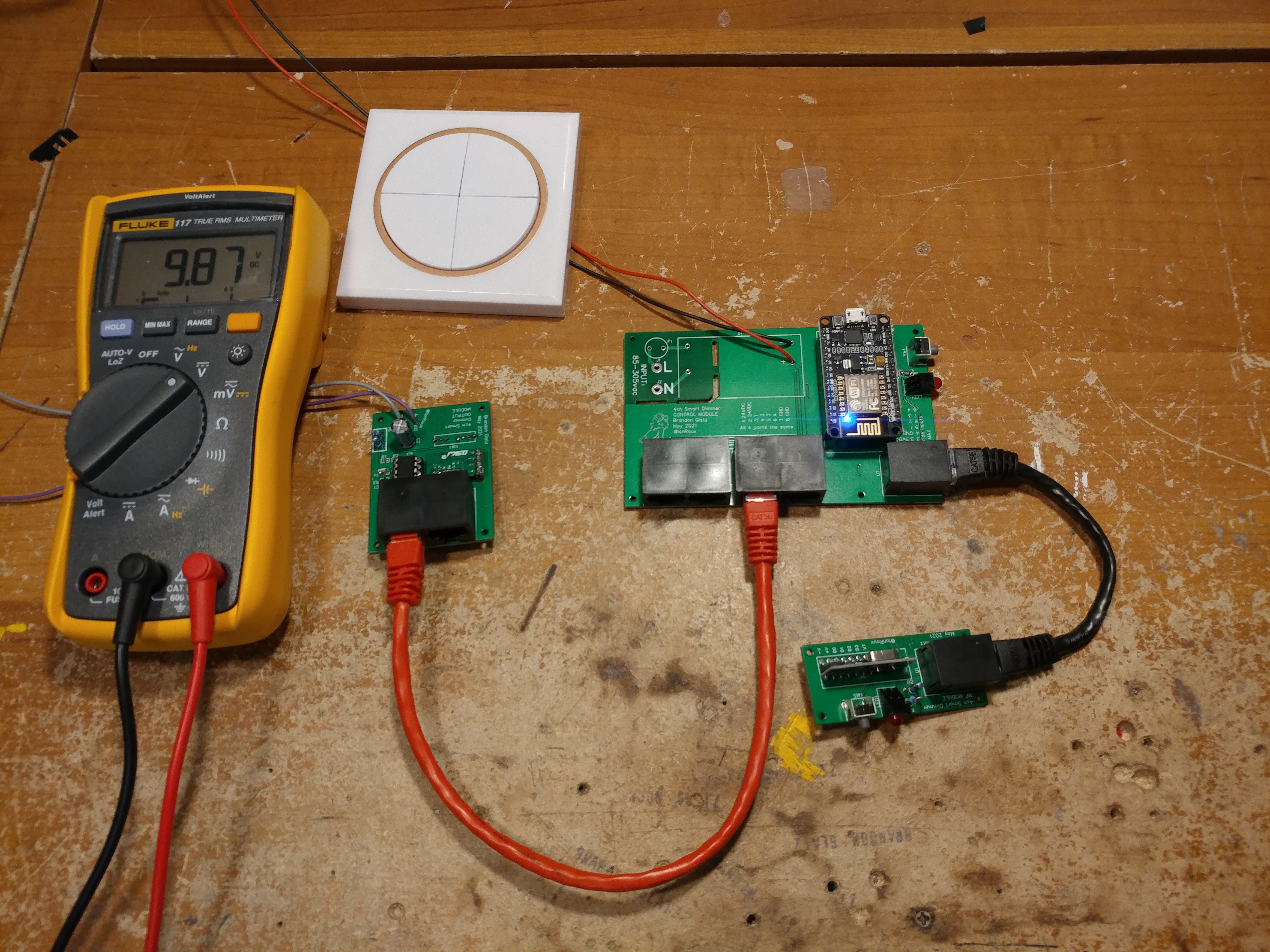
Finally received almost all of the parts so I went ahead and assembled one of each. I forgot to order the potentiometer and 4 position switch for the output modules.
After some tweaking I finally got it working. I managed to make a mistake on all 3 boards:
- Controller Board
- Power supply footprint was incorrect
- I really should not have used SMD devices as there was plenty of room. I ordered a stencil but forgot that all but one resistor were on the bottom layer so I got a stencil with a single hole. I'll redesign it to use through hole.
- Output board
- Really the only issue with this one is that it also uses SMD, but since I will need to make 10 of these I think I will let that go.
- I may change the resistors for a resistor network as there are 3 of the same value on here and that would speed up building.
- RF Board
- I use EasyEDA for designing my boards and frequently make use of the community submitted component designs. I did not notice that the upright resistor footprint that I used had the pads as non-plated by default. I have used the upright resistor footprint in a few of my other projects which means they would have the same issue. I never noticed it because those must have all been routed on the bottom layer. This board has one track going to the bottom and another leaving it at the top layer. Easy fix, but frustrating as that is the only problem with this board.
I'm going to make corrections to the boards and get them ordered. After that is done I will start using the ones I assembled to design the cases for these. For now I plan to just make them 3d printed. The conduit connection will be a half inch conduit chase nipple as most lights have half inch knockouts for wiring.
Either way this is a big step forward for this project!
Discussions
Become a Hackaday.io Member
Create an account to leave a comment. Already have an account? Log In.