brandon
-
Programming while waiting
05/09/2021 at 04:45 • 0 commentsWhile waiting on the opamps and other components to arrive I began work on the program.
I found a few examples online but not many of them supported dimming or had really clunky methods of making the device smart including having to set up an MQTT server. I appreciate that those can really make a device connected, but I did not feel it was worth it just for controlling lights. All I wanted was to be able to control the lights with alexa.
I eventually came across a video by Tech StudyCell on youtube that did exactly what I wanted: https://iotcircuithub.com/esp32-pwm-led-dimmer/
This used the Espalexa library and presents itself as a simple dimmable light.
The example code only supported a single light and had a pot for use when the esp could not connect to wifi.
I modified the code so that it had 4 output channels and supported 4 inputs so that a manual button could be added. The button would cycle between off, auto (smart), and on. If you use the manual button to turn the light on or off, the next smart command will override it to prevent it getting stuck in a certain state.
I'm not ready to post the code yet as it is still very hacked together and messy while I am in the middle of the project. Once I have functional boards I will clean it up and share it.
I was able to successfully get alexa controlling the brightness of 4 led. The 5th red one indicates if wifi connection failed.
-
Starting from the end
05/09/2021 at 04:35 • 0 commentsUnlike most of my projects, I decided to design the circuit and PCBs first before any testing or programming.
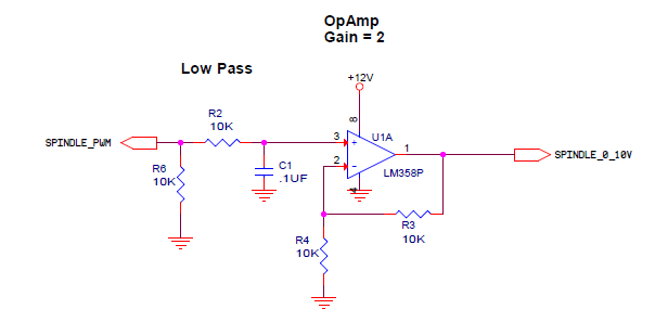
I found a circuit example to produce 0-10v analog voltage signals from the pwm using an opamp:
![]()
This was originally designed to control a spindle and was designed for use with an arduino. The x2 gain means a 5v pwm would output 10v. The ESP is only 3.3v so I changed R3 to be 32K. This gives a slightly higher than 10v at full on but the lights are tolerant of up to 12v and 32K is a common value.
I bought some opamps and while waiting for them to arrive so I could test my idea, I started on designing the circuit boards.
Here is a timelapse of the board design:
My initial design was to have the ESP + opamps all on one board called the "control board" and have the 0-10v signal for that go out to the lights over RJ45. The modules at the lights would have two RJ45 ports on it to allow daisy chaining between multiple lights, as well as a 4 position switch to select which of the 4 dimming channels that particular light would be controlled by.
-
The idea
05/09/2021 at 04:25 • 0 commentsPlatt had a big sale and I found that they had some LED panels for drop ceilings. I have always wanted these in my office/workshop
I plan to put 3 in my office and have them individually controlled due to where they are and 4 more in the other room all controlled together.
![]()
The only few wifi smart dimmers I could find only supported 2 lights each max so for all of this that would be FIVE devices on my wifi just for lights alone. I could not find a multi channel controller and this is obnoxious so I decided to make a single dimming system made from an ESP8266.
Custom ESP8266 4 channel 0-10 dimmer
Smart dimmer for 0-10v lights without needing 4+ devices on wifi