-
First spot!
05/23/2021 at 17:33 • 0 commentsI've been trying, on and off, to make a QSO but the output power of the DDS is just too low to be heard. I'd just about given up until I managed to get an FT8 packet received by a station in Germany - about 900km away - on 20m. Not bad for 10mW or so...
I have one of those "45W amplifiers" (found cheaply all over the Internet) knocking around, so the next plan is to use it to boost the output of the DDS. First I'll tweak it slightly to bring the power down to 5-10W (the most I'm allowed on a Foundation Licence) and hopefully also lower the risk of popping the transistors.
I've also just realised that I can adjust the output power of the DDS chip by sticking a trimmer pot where Rset should go, giving a means of controlling the output of the PA once its connected.
-
Yaesu emulator
05/15/2021 at 18:37 • 0 commentsToday's coding fun was all about adding CAT functionality, so that JTDX, WSPR-X, and so on can all interact with the transmitter just like a real rig. After a bit of choosing I settled on emulating the Yaesu FT-450. The CAT commands are well-documented, though debugging without any way to see what was passing over the serial port was a bit of a git. Got there in the end.
So now the transmitter jumps frequencies whenever you change bands in whatever software you're using - sweet. Or I can manually change frequency by sending an ASCII string like "FA14074000;"
-
SPICE-ing things up
05/14/2021 at 17:37 • 0 commentsHad a bit of a muck about with LTspice, but can't seem to work out a way to gang the DAC outputs together to get more power - the balun approach doesn't seem to work*.
However, what I did find is that the filter supposedly on the module is a bunch of junk - certainly not suitable for driving a notionally 50ohm antenna. A better one might be:
C2=C4=C6=22pF,
C1=C7=33pF,
C3=C5=82pF,
L1=L2=L3=100nH
together with R4=51ohms, R5=no fit, R6 (Rset)=1.95kohm. Oh, and a series DC blocking cap somewhere.
LTSpice then gives the output power around 20mW (+13dBm) and rolls off at about 70MHz. When I next get into work I'll swap all the components over, and stick the output on a power meter and see...
(*update: oh hang on, maybe I've just worked out a way to get ~38mW (+16dBm) out?)
-
more testing
05/13/2021 at 18:27 • 0 commentsLooks like WSPR will work too. Just tried the same test as last night - namely using a .wav recording of a packet to drive the transmitter - and the PC software happily decodes it.
Next step is to try and squeeze a few more dBm out of the synth. I have a plan to bodge on a 1:1 balun on the outputs of the synth so that both pins are combined (double the power?). Also might try changing Rset to get them to drive more current. Maybe get a whopping 3-4dBm this way?
Finally I need to fit a TX/RX switch (a cheap 5V relay) driven by one of the Arduino pins. This then disconnects the SDR dongle, and connects the transmitter, whenever the PC makes a tone - i.e. we want to transmit.
-
Early success!
05/12/2021 at 19:41 • 0 commentsThe AD9850 module arrived today, so I quickly set about hooking it up to the Arduino. A few wires and a few lines of (stolen) code later, and I had it producing CW.
Then it was an easy step to integrate it with the frequency estimator code from yesterday, and hey presto!
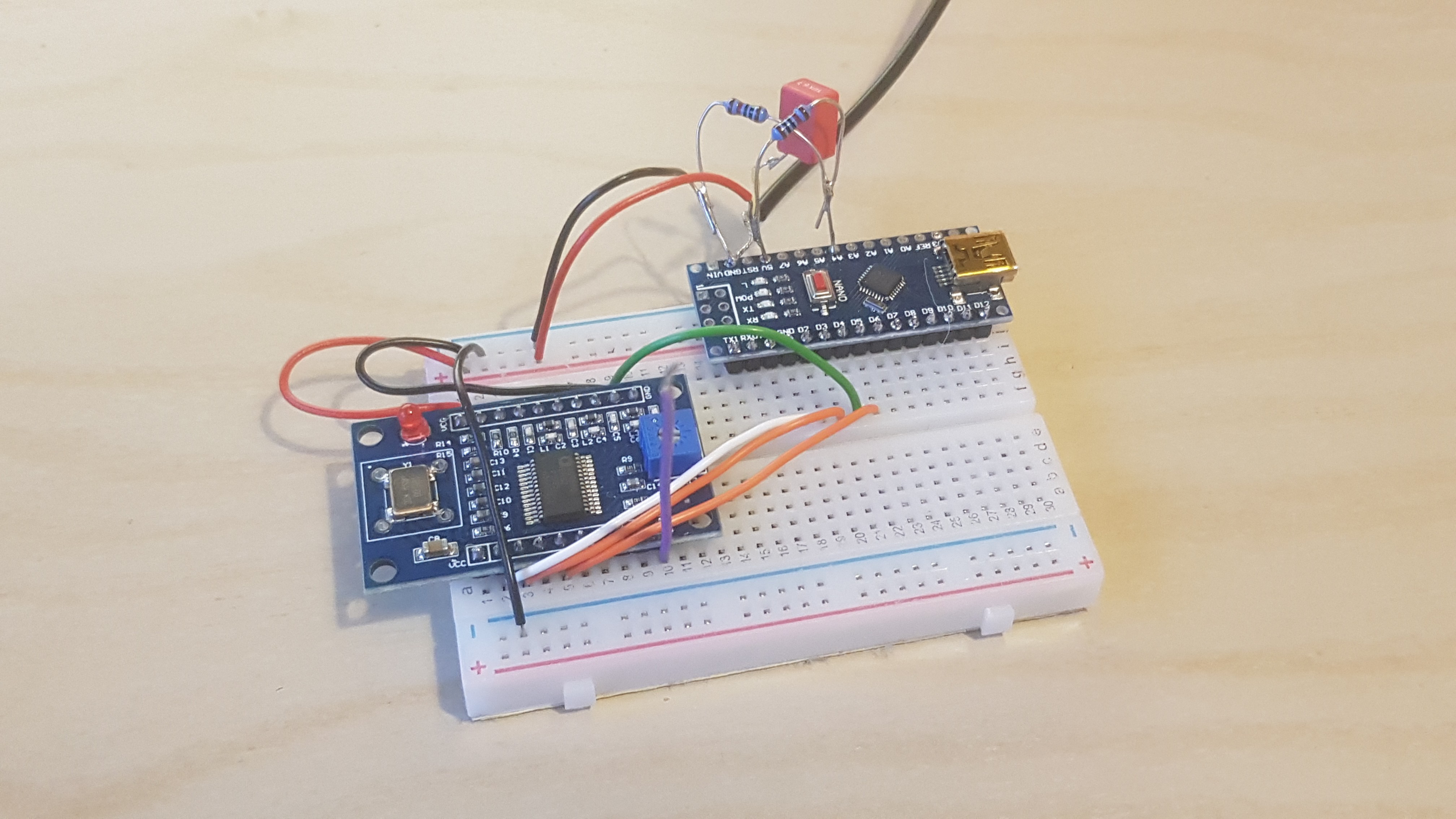
Here's a pic:
![]()
Photo of the breadboarded DDS and microcontroller. Using a .wav file recording of FT8 audio, I was able to produce a real FT8 transmission (on 14MHz) and JTDX was able to receive and decode it - worked first time. Not only that but my 'blob' on the waterfall looked just like everybody else's, suggesting that the RF spectrum being produced is nice and clean.
Now let's remember, the output power is very feeble (only a few milliwatts), and I have no antenna connected yet, so there's still work to do...
-
First step: frequency estimation
05/12/2021 at 08:52 • 0 commentsA key feature of FT8, WSPR and other waveforms is that the FSK tones are very closely spaced in frequency (compared to, say, the kind of FSK that an ISM-band device might transmit). Also, they change relatively slowly - only a few symbols per second, if that.
The first step, therefore, is to be able to very accurately (<1Hz) estimate the frequency of an audio-frequency tone that is presented to a pin on the Arduino. And to do this quickly, certainly less than 100msec.
The approach I've taken is to count rising edges (Ne) whilst simultaneously running a timer (f = 2MHz). After the measurement period is up, the frequency is simply f x Ne / timer_value.
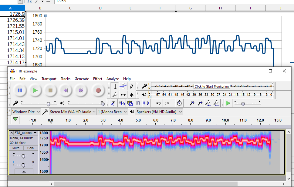
It took a few hours of messing about with timers and interrupts, but finally it's working very nicely. The plots below show the measured frequency output for a given audio input.
Comparison of the frequency estimator output (graphed in Libreoffice - top) versus the spectrogram of the original audio (in Audacity) for an FT8 packet. (Note: audio signal is applied to the Nano pin via a series capacitor (DC block) and resistor divider so that it is centred mid-rail.)

