I started with a design of Andrew Levido that you can find it in the links below.
Then I adjusted parts until it fits my requirements.
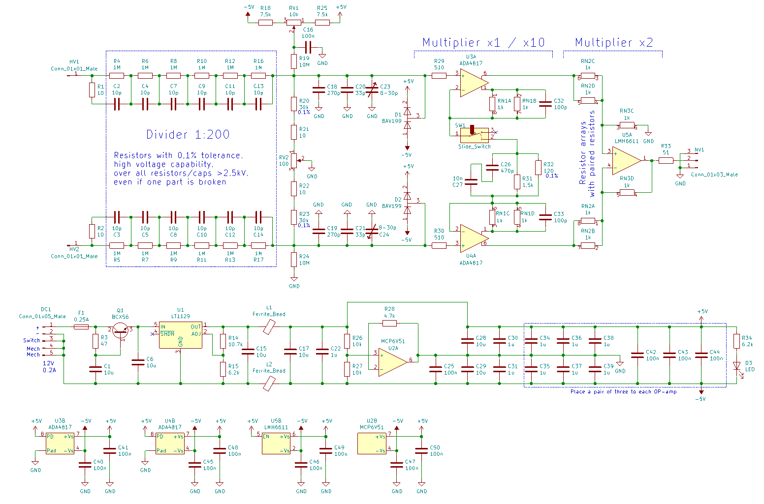
The first step was to change the frontend from four to six resistors and capacitors in series. I wanted to use SMD Parts and 1206 is a good available size. But to get enough voltage strength four parts in series is a bit small. With 1206 parts you can use 1,5mm gaps wich is great for the creeping distance.
The second step was the supply of the probe. I don't want a battery because in my experience it's always empty when I need it. So I decided to use a barrel jack input. I added a capacitance multiplier and a LDO-regulator for filtering, a bigger voltage range and reverse polarity protection (LT1129). I got the LT1129 cheap from eBay, else it's a bit expensive. With a 12V supply I get about 10,5V for the op-amp wich divides the supply in +/-5,25V. I got the idea from Bud Bennett's project (https://hackaday.io/project/169390-a-10x-100mhz-differential-probe). The probe should also work with 15V or 18V. If the voltage is to high the LT1129 will protect itself with its overtemperature protection up to a voltage of 30V.
-> Schematic completed, you can find it below beside the BOM.
Now it was time to think about the connection of the HV-input and the BNC-output. I decided to use safety banana-plugs, that are specified for 1000V. For easier connection I didn't use sockets, but wires with the plugs at the end. The same decision was made with the BNC connector.
The next step was the layout. There were multiple things to observe. At first the frontend should be routed symetrically. Then the ADA4817 has layout hints (like no ground plane under the op), that must be followed. The LMH6611 is not that critical, but the complete analog circuit must be free of interference. The last part is the supply which should be as wide away from the rest as possible. For low impedances I used a plane for ground (but not under the ADA4817), another one for +5V and one for -5V. Also important for safety reasons are the cuts in the PCB, that increase the creeping distance in the frontend. All in all it should be enough for 230V AC (but use it on your own risk!).
-> You can find the layout and the gerber files blow.
Update: LT1129 footprint is wrong, should be TO-263 (D2Pak), but is TO-252 (DPAK)
Update 06/02/2021: Pin assignment of the BAV199 diodes is wrong
Update 06/06/2021: Two capacitors were not connected correctly
The 3D case is now ready for download. I developed it with FreeCAD and printed it with a creality ender 3 printer and PETG material. Be careful with the switch, it must be soldered very accurate to fit through the hole. I added a picture in the gallery with the case.
06/02/2021 Update: Added a hole for the LED and some deepenings for the trim potentiometers.
06/07/2021 Update: First working prototype, i made some hotfixes against the mistakes above. Schematic and layout are now fixed, resulting in V1.1

06/12/2021 Update: I changed the case a little bit. The height was increased about 1mm so that no parts are touched by the case. The four mounting holes are now perfectly for M3 16mm flat head screws.


