...yyyyyyyeeeeaaaahhhh....
I Had somewhere in all this mess forgotten the link-port's limitations.
I need one input and one bidirectional.
Two wires, right?
OK, but, my bidirectional signal is open-collector and pulled up to 7V, possibly 12V, at the device-side.
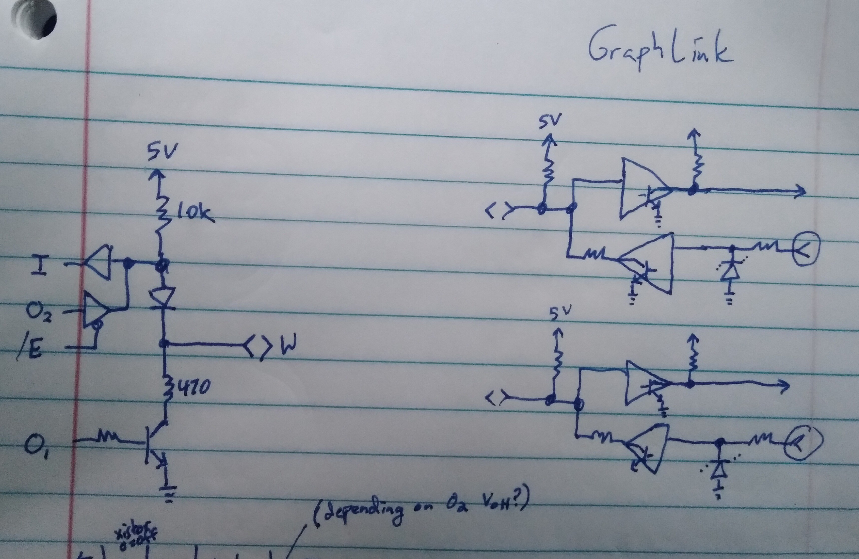
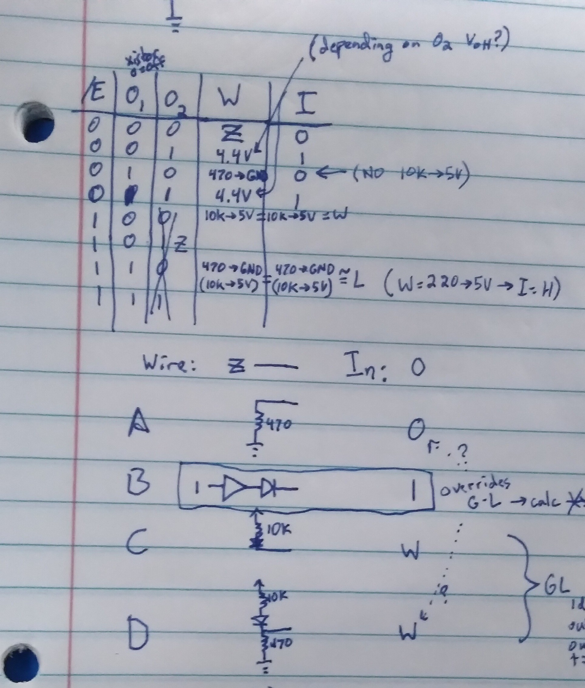
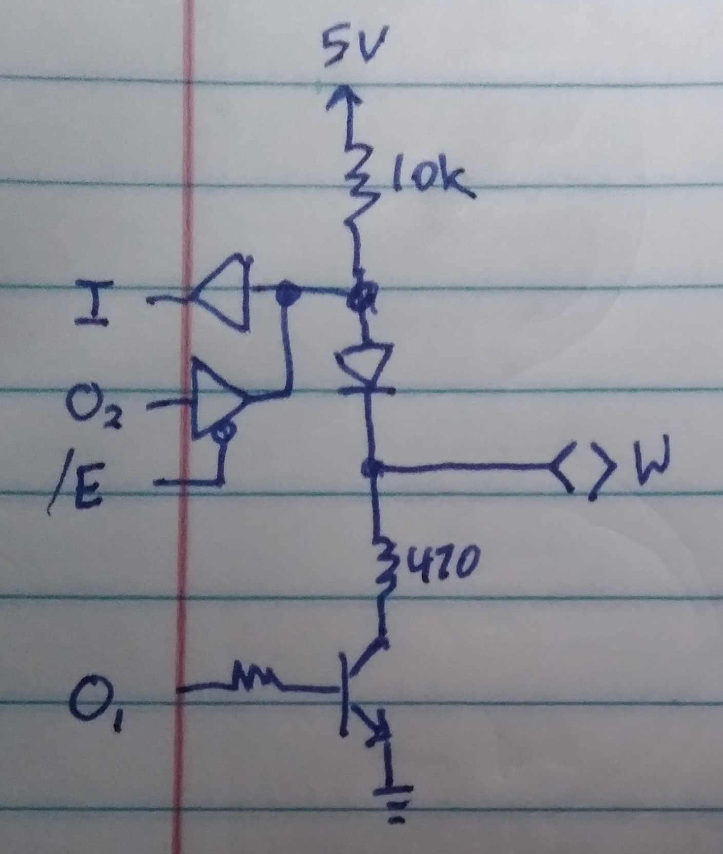
I'd been planning to use the graphlink->DB-9 adapter as a level-shifter... but this creates a problem. If I wire the graphlink's output to the same linkport-wire's input circuit, then we create a latch. When the device sends a low, the graphlink latches it.

I thought maybe I could use the two separate linkport wires for input and output for my bidir signal, then the one used as an output there could be multiplexed for the other signal's input... but, the wiring of the graphlink and linkport would feed that signal back out to the bidirectional wire. No good.
OK... so, The way the linkport works, it /is/ possible to drive the wires with a real-ish "high" rather than the usual pulled-up... that could be used to unlatch the low latching...

If I throw that in my bit-sampling delay-loop, I think it'd make my loop 44T-States, which is around about 9us... At 10.4kbits/sec, that's at-worst about 10% of a bit-duration, and usually one would sample a bit at about 50% anyhow.
So, as far as a typical uart signal goes, this'd probably work.
OTOH, I don't have a lot of info about this bidirectional-one-wire UART... it's entirely plausible (as in most bidirectional one wire serial systems?) that the device watches the wire to see if it's following what it's sending, and if not, then it gives up the wire to what it thinks is another device talking.
Dunno, here. So, with this setup/idea, its low bits will be extended by ~9us... which could be a problem.
I could plausibly speed that up a bit by going back to sampling, and post-processing, but, still, it'd extend those low bits several us.
.....
An alternative is to wire both signals /directly/ to the calc's link port... all 12V of it.
And, actually, it almost looks like that'd be acceptable. But I really don't like that idea.
But... I mean... Why not? It's all well separated from the CPU... diode-protected...

Hmmm...
....
I'm also feeling exceptionally overwhelmed with what all's necessary to put all my code together. I've got the clock-sampling, but presently it loads that to a screenshot. I've got the clock-rate calculator, but that takes it from a screenshot. Merging those and removing the screenshot bit /should/ be easy, but that never seems to work out that way.
From there, I need to calculate the bit durations, and I've already figured that out... per last log's ramblings, friggin NumSamples*84/NumClocks.
Ahhh, right. Still need to write that division function. Easy-peasy, right?
Multiplication I thought was done days ago, turns out it was buggy. Fixed.
Then, feed that to my T-State delay function (which may need to be modified to unlatch the input).
Then stick that in the UART bitbanging code. Both transmit and receive.
Then... protocol... which is allegedly documented, and yet every doc seems different.
And, again, this system is request/respond, so if my request isn't right, who knows even /if/ I'll get a response.
Why do I feel so daunted by all this /now/?! Coulda gone through that weeks ago, before all this work.
...
Ahh, yes... AND, I'd been planning some testing via a computer's UART... 9600baud. But... hmm... that too is quite daunting. First-off, simulating my clock-source... I suppose I could send a burst of 10 0x55's from Compy, that'd pretty much match the 49 clocks from the other system. But, I should probably try it at a higher rate than the 9600... but, of course, every RS-232 bit rate is an integer multiple of the others, so its not a /great/ test. And, Of course, it's not single-wire, nor open-collector, so this "simple" test is starting to become a bit of an ordeal. Especially considering testing the delatcher...
...
Gah! The delatcher has to delatch at the /edge/ of the bit, but I'd rather sample near the middle! That means two separate delays per bit?
No... wait... I thought about this, didn't I? No, the delatcher works as long as we're in the delay loop. OTOH, the delay loop only runs for about 30%(less?) of the total delay between bits, the rest of the delay time is occupied by setup for the delay, shifting-in the bit, storing the byte, etc. hmm, this could be iffy. So ideally the delay loop starts just before the bit edge, then completes near the middle... hmm.
This project is /really/ pushing Calcy's limits. Heh. And mine... i've lost so much steam these past few days.
...
Division function complete. Also started breaking the big pwm/clock-sample-parser program into pieces for inclusion elsewhere... then it hit:
Save tPrsPWMS -> bPPWMS2
"ERROR: MEMORY"
as I recall, it didn't even say memory-full... just "Memory". Like it would've used up RAM to store the word "Full" in the ROM? Heh.
OK, first: kinda funny I /just/ mentioned pushing poor Calcy's limits... then hitting one.
Second: WOOHOO! This is a big moment!
Think about thumbtyping 92KB of assembly on a 30x8 character display! Ok... well, that includes a few backups (remember, though, I just sorted through those and removed them /all/ a few days ago) and also a few KB for ZAC and Asmide86, oh also 3KB for screenshots... Oh, and the compiled executables, themselves... OK, maybe I've thumbtyped half that, still 46KB ain't nothin to scoff at!
...
FYI BAD IDEA to use ZAC/Asmide86 when the memory is nearing the limit....
Open File, typed-up some changes, save, "memory", "whattya complaining about, it says I've got 2K free!" gone.
I mean, it's not good practice, anyhow...
Have not at all been in the mood to hook up the computer to backup...
And, actually, shoot... i mean, I'll have to unload some stuff. Hah!
Didn't I add FLASH for just this sort of thing?
Still... gotta code up the transfer utility... and that means I needta make space for coding. Heh!
 Eric Hertz
Discussions
Become a Hackaday.io Member
Create an account to leave a comment. Already have an account? Log In.