Eric Hertz
-
While I'm backing-up...
09/10/2021 at 17:43 • 0 commentsBrief (yeah, right...) recap...
What I need is a somewhat-accurate reading of the CPU frequency so that I can bitbang a bidirectional UART.
This differs from my previous "UARto[S]T" (Universal Asynchronous Receiver to [Synchronous] Transmitter), because for that I was able to control the interface at the byte-packet-level at the computer-side, using the computer's data transmission as a clock for the calculator's data transmission. This time I don't have that luxury, so need a "real" UART implementation which can read and write packets which actually are truly asynchronous. ...Well, mostly.
The idea, then, comes down to watching /another/ communications port, and deriving timing from it.
That port is not a UART, nor does it communicate at a similar baud. But, it /does/ have a defined and steady-enough bit-rate, such that if I can count/calculate the number of calculator CPU cycles during its bits, then I can get a pretty accurate idea of how fast the CPU is running. And, from there, can add appropriate CPU-cycle delays in my UART bitbanging.
The logic-level-toggling-rate of that comm-channel, however, is /really/ fast, in comparison. So fast, in fact, that, at least in my z80 skill-set, I can /just barely/ guarantee that every high and low will be detected /at all/. Nevermind trying to measure their duration.
On the plus side, every bit in that protocol has both a high and a low, so clocking is inherent. Also, once a packet is started, all its bits flow back-to-back, even between bytes.
So, I plan to store several hundred samples at a known sampling-rate of 21 CPU cycles, then count the toggles. That'll get me a pretty good idea of the CPU frequency, at the time those samples were taken. I figure it won't vary /dramatically/ thereafter, at least for a few UART transactions, then I can do it again.
Also, luckily, the UART system only communicates after the calculator requests it. So, there's plenty of time to measure/recalculate timing whenever necessary.
...
But, that means processing samples... and I thought it might be handy and easy to do-so with those I'd already taken as logic-analyzer screenshots...
And, I somehow managed to corrupt some data in places that have nothing to do with my project. And now it's acting /really/ weird. So, memory-reset again, despite all those wonderful "Memory Recovered" messages.
That flash backup thing would sure be handy!
...
On the plus side, this other stuff has helped get ready for that, I now know a thing or two about accessing/creating "variables" which includes things like programs and source "files"... so, actually, it shouldn't be too difficult to write that backup/restore utility... yahknow, I imagine a day or two, so it'd probably be two months.
...
Multitasking bit me in the butt...
I recently acquired from a garage sale an external hard disk large enough to backup my internal drive... So I've been writing zeros to it in about 40GB chunks whenever I've got the compy running for other purposes... make sure there's no bad sectors, whatnot.
And, I'd forgotten my internal drive is connected via the same USB hub. Which meant, in this case, that connecting the external drive /before/ power-up could (and did) cause /it/ to be /dev/sda, instead of the boot drive...
'dd if=/dev/zero of=/dev/sda seek=200G'
Yeah, i noticed, thankfully, about 1.5G in because (again thankfully) it was running much slower than usual. And, looking closer, the wrong hd light was blinking. I do like hd lights.
So... shit. Now I'm learning about debugfs and ext4 block sizes and inodes... some 250,000 blocks means potentially up to 250,000 files (especially considering all my small sourcecode includes, or the friggin 512Byte sectors from #OMNI 4 - a Kaypro 2x Logic Analyzer ). Thankfully I do have another backup drive to recover many/most(?!)/all(?!!) of them from, but first I have to figure out which files were zeroed!
So, first yah gotta calculate where the drive's physical sectors are in the partition, then convert those to filesystem blocks... then use debugfs to find out which inode is associated with each block... then you can ask the filename/path of each inode.
So far I have a list of used/unused blocks. From there it takes nearly a minute to convert 100 block numbers (of ~250,000! 2500minutes!) into inode numbers. I /might/ be about halfway through that process, maybe, yeah, probably not, after many hours. Recall: I can't just leave this running overnight, lest I run out of juice! So, I've got to break this process into chunks. Heh. I've a list of it looks like nearly 100 inodes/files so far. I looked a couple up and they're photos from 2017. ...which most likely are of the closest friend I've ever had, who I lost last year. I'm definitely not OK with losing those too. But, on the plus side, the bigger they are the fewer need to be found/recovered. There's probably a couple multi-hundred-megabyte videos in there too. But, it seems, it still takes about a minute to associate 100 blocks with inodes, even if they're all associated with the same inode. Heh.
This brings me to another question, which /maybe/ I'll test... I use rsync to backup my drive... I wonder if it's thorough-enough (how could it be?) to check whether the file's /contents/ changed, when none of its metadata (size, modification date, etc.) has. It can't, I don't think, be set up that way, otherwise it'd have to read the entire drive's contents in the about 45min it takes to do its incremental backups. So, I think, it probably wouldn't even notice they changed.
That could be beneficial: I could try an incremental backup, now, /after/ the disaster, then do a full restore. Hmm...
But, again, 320GB at 480Mbps/2 and on a battery... and /that/ backup drive has to run off the inverter... I don't like running it for more than a couple hours. And starting the engine to recharge causes the inverter to kick out...
Another alternative, if somehow it /did/ notice they changed (maybe it can look up the checksum more quickly?), would be an incremental backup, then looking at the logfile to see what's changed.
Maybe realistically I should do that backup sooner rather'n later, anyhow. I don't think I have since I started this TI-86 project. Oof.
The new drive is also 320GB, /and/ USB-powered, /and/ slim/laptop-sized... So the idea was I could run backups on it far more often without all those power limitations. The drive could be kept identical, so could even be dropped-in if the other fails. Almost like a mirrored RAID. Though, I doubt there's an option in rsync to do it at the byte-identical level... and I've no idea how to track and then dd small changes, heh. It's not /highly/ important, but could've been handy in a case like this!
Sheesh I'm stupid sometimes.
...
Oh, I /did/ manage to finally parse the logic-analyzer screenshots... wow that was a mess. It should've been so easy. But, did not yet get to parsing the frames/packets, and most importantly /timing/, which, of course, I thought was going to be the hard part. I had that pretty well figured out on paper... with a few calls to getNextSample() which, I'd of course change from grabbing from the screenshot to grabbing from the sample buffer, once I was ready to put it all together... grabbing from the screenshot was supposed to be easy! For early testing! Heh.
On hold.
Back to data recovery.
...
Another day, making nearly a week, and finally I think we're back where we started... Data recovered... about 800 photos, many/most of my cat who disappeared last year... It hurts every day, and after a year of searching I still regularly feel tempted to go try again. I dunno what to think about the slap in the face that came soon after I called off the search, almost losing those photos too. Nor the friggin' irony that it happened *as a result* of implementing preventative measures against such things! But, thankfully, earlier such measures-taken were enough, this time. Frankly, it feels to me, that exact same kind of irony is what resulted in his disappearance. And similar for so many other such prior disasters. Oof.
Anyhow, it seems I was able to recover all the lost data, after several days of 100% CPU and quite a bit of hard disk activity dedicated to nothing but figuring out /which/ files were zeroed... after that was figured-out, it was simply (hah!) a matter of deleting those and copying back the originals from my backup drive... that all, actually only took a few hours, despite my flakey script and having to redo it several times. Thankfully it wasn't /too/ flakey, this time. Whew.
BTW: when bash-scripting:
While [ 1 ]
Do
Read line || break
...
Cp -i sourcefile destination
Done < fileListing.txt
BAD IDEA.
When cp asks for a user response, it gets it from fileListing.txt rather than stdin.
And, I found out, "1" is the same as "yes" in the "overwrite existing file?" prompt.
BETTER:
While [ 1 ]
Do
Read line <&3 || break
...
Cp -i sourcefile destination
Done 3<fileListing.txt
Notice the 3< and <&3
I'm not a newb... I learned that probably a decade ago. The things we forget...
(Iirc, 2, instead, would've redirected stderr, 1, stdio, so 3 is the first that isn't typically used by the system for special purposes).
What else...?
Did some mathing during the dayslong automated search for zeroed inodes...
It seems my TI-86 is running around 4.7MHz. I coulda sworn 6 was the magic number. I've been on the same set of dollarstore batteries for a surprisingly long time, and that may be part of the reason... OTOH, I have only barely begun to increase the contrast, at least as far as I recall having to regularly do with name-brand alkalines in my TI-82 days. Huh.
And I started to work-out the T-state-count delay function for my bitbanging the UART.
Last time I did similar was on an AVR at 20MHz... in C...
Therein, i had a UART input and output bitbanging function, a keyboard matrix decoding function, a realtime audio-sampling function, and an SD-card writing function all running round-robbin... fast enough for 10bit audio sampling at 11KS/s. Heh!
Herein, I think I can /only/ handle the UART, and /only/ one direction at a time. And, instead of checking the timer to see if it's time to handle the next bit, I'll have to insert a blocking delay-loop between each bit. Heh. Some 400 clock cycles between bits /sounds/ like a lot, but this simple spin loop, only three or so instructions, will take well over 20... certainly not enough time to jump to another function, determine which state it's in, process that state, then return.
I'm constantly in awe of just how much faster the seemingly lowly AVRs I've spent most my adult years working with (while my peers keep insisting on ever more processing power) are than full-fledged CPUs still in use in the same decade.
And, further, that, really, it's not so much about the underlying transistors' abilities, but more about the design. 7400-series logic was capable of 20MHz in the z80 era.
But, even if we were talking 4MHz, the fastest z80 instructions are 4 clock cycles. 4 times slower than the vast majority of AVR instructions.
I really think something like AVRs /could've/ existed in the z80-era, if they'd just thought that way, then. Exceptions, of course, being in transistor /count/ (MAYBE, seeing as how many were necessary for things like processing variable length instructions, microcode, bus handling, etc.)... And then, of course, memory. I think the Harvard architecture of AVRs probably makes things much faster, since two separate busses are accessible simultaneously. But, again, back then workarounds could've existed for things like slow memory access times by, say, splitting the memory bus into a state machine: request an address, expect the response four cycles later, meanwhile another access could be requested... they already had /multiple/ chips per byte (remember those arrays of DRAMs on the motherboards?), if instead of tying all their address lines together, they'd've added two 74LS574 latches to each bank of 8 DRAMs, they could've had 4 times the access speed!
Funny thing to me is that, I think, many such design ideas /were/ implemented back then... just never really made it mainstream. Maybe in things like Cray, etc. But, at some point, I guess, it was mostly market-driven... compatibility was important, thus 8008->8080->z80 having the same backwards-compatible instructions, similar timings, similar busses... nevermind, of course, implementation complexity... 40-pin DIPs were apparently highly desireable over 100pin doolybabs. Yet, they /obviously/ had the spare transistor-space to design-in significant, near "supercomputer", levels of circuitry, had they chosen to do-so in the computing side of things instead of the bus-interface side. Then, supercomputers were still being built at the gate-chip-level! Weird to think about.
Anyhow, somewhere in there I get ideas of how to improve the device's abilities, like my "24-bit quick-mapper" idea, or using DRAM refresh cycles /for/ DMA... and it could be interesting to actually build such a system with a real z80 and a slew of TTLs... and some arshole will suggest an FPGA, and then I mightaswell do RISCV and forget about all this.
And, anyhow, none of this has to do with my UART task, which I'm kinda dumbfounded to think it'd actually pretty much /require/ spinloops for 400 precious clock cycles! Surely those could be put to better use!
...
...
Time for a new backup of my drive, now that I recovered those files... last backup was July 12. Ironically, looking at the notes, that was when my PiZero (my main compy's brains) decided to bite the dust. Well, several days prior, when I was... trying to run a friggin' backup.
Thankfully, I had a new PiZero sitting around for another project which has yet to happen... that project was years in planning, but pretty much started and ended the night my cat disappeared.
So, once I finally got the new Zero soldered-up, I immediately ran that backup that killed the previous one. And... apparently that was my last backup until today.
I've done a lot /on/ the TI-86 in that time... And have done many backups of it onto the pi's hard drive. But, really, I think that's about all that's new on there... besides, of course, recovering those zeroed files, which, if i did it right, the backup system won't even notice, heh. Except that I also hardlinked those files into a new folder so I could easily see what I'd recovered. Which, seeing, isn't really so easy, being still too fresh wounds.
...
Huh, I had something else TI86/UART-related to mention, but i lost it...
Back to UARTing!
...
LO friggin L
Backup failed.
Right, forgot my battery appears to have a dieing cell. 10V is too low for the inverter.
Hah!
Next time i feel like idling the engine for 45min, then... I knew there was a reason I was kinda stoked about a USB powered backup drive. But /that/ first backup will take /many/ hours... days, probably... and have to be done in many steps. And, I wasn't planning to use my same configuration for it, since it's the same size as my main drive, I was planning to essentially mirror it, rather than keep old backups... so, more days setting up the new config. Heh!
...
JESUS!
22MIN is too fast...
It was 45 last I recall.
Now, comparing to my July backup, there are nearly exactly ONE MILLION FEWER FILES. We're talking: it was some 1930 thousand before, and is now 990 thousand.
...
What did I DO?!
...
Gather thoughts...
OK, I vaguely recall doing a bunch of cleanup... Specifically: #OMNI 4 - a Kaypro 2x Logic Analyzer had dozens of copies of each sector in individual files... the disk was 400k, that's 400,000/512 or some thousand files per attempt.... but, surely i didn't have a Thousand copies... dozen, dozens maybe, but nowhere near a thousand.
Shit, where's all my files?!
-
TI-86 Logic Analysis
09/03/2021 at 18:10 • 0 commentswhelp... I managed to speed up the sampling rate dramatically...
My signal is /supposed/ to toggle (or not) at 8us intervals...
My original sampling code took 39T-States per sample, or at 6MHz 6.5us/sample... IF I understand the z80 right...
![]()
![]()
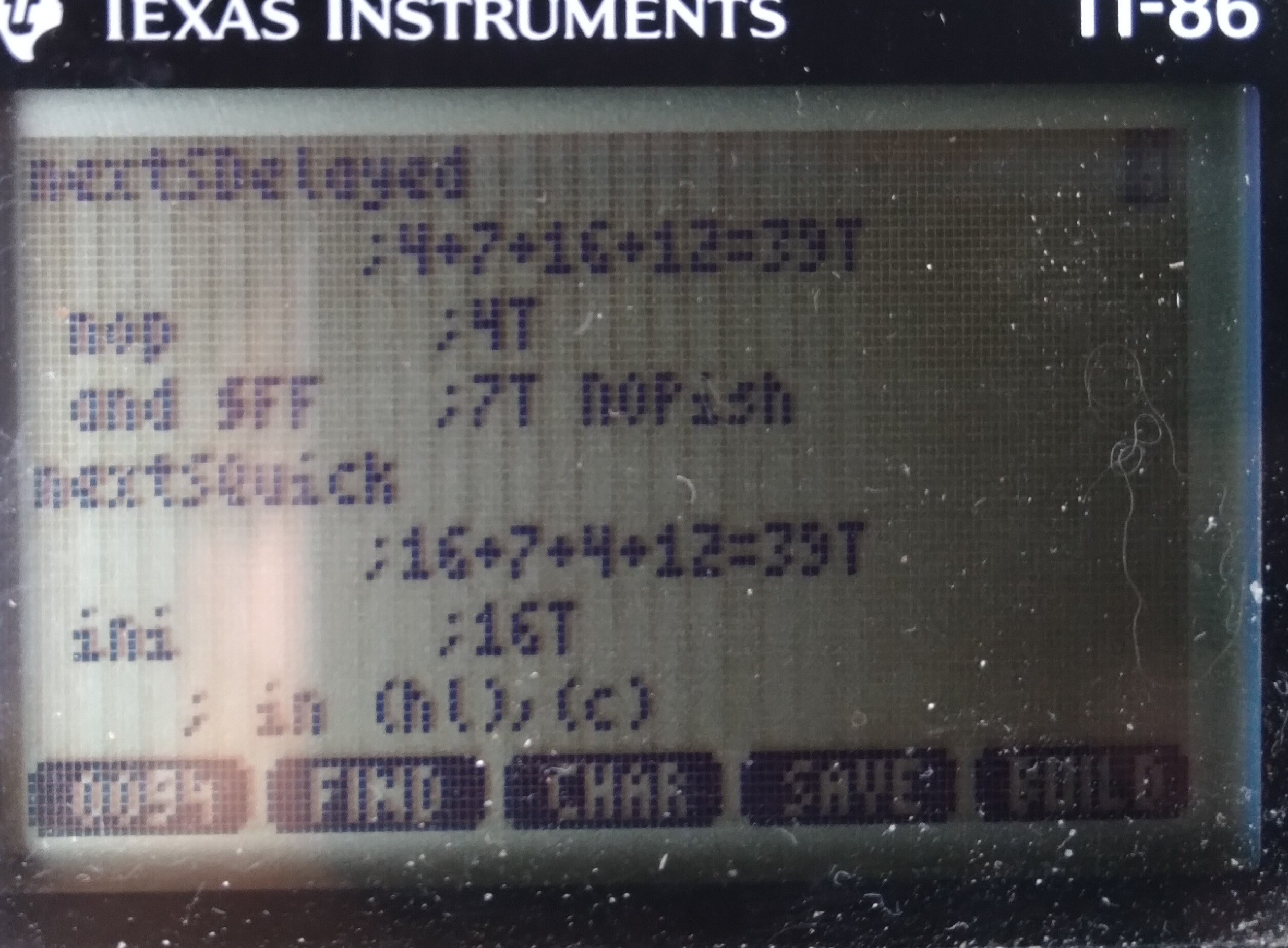
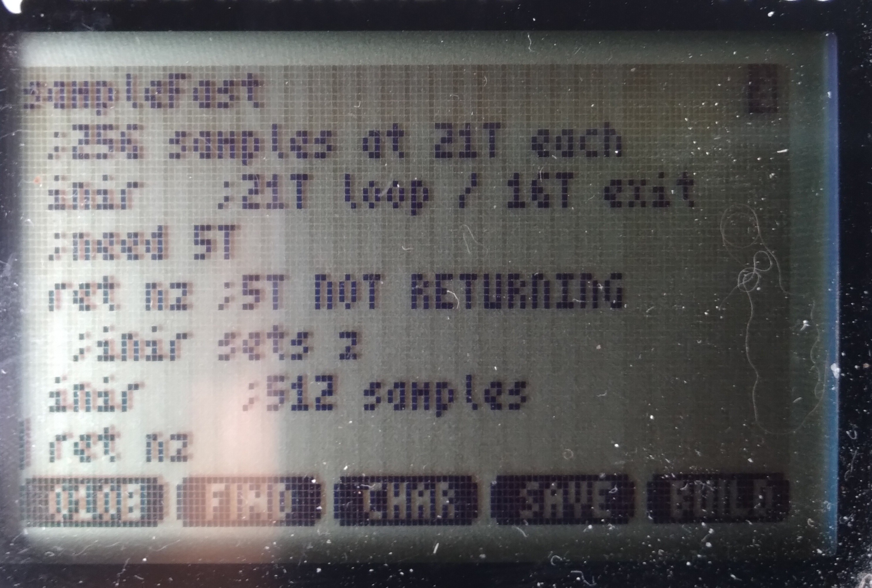
The new code doesn't use a loop. INIR takes 21T states for each of 256 samples until the last one where it takes 5 fewer, since it doesn't repeat/loop itself.
So, presumably (I have Very Little to go on, here) if I insert a 5 T-State "NOP" between calls to INIR, then samples would be perfectly spaced in time, even crossing from sample 256 to sample 257. Thus each sample now takes 21 T-States, or 3.5us (at 6MHz). Right?
![]()
Now, at 3.5us/sample and 8us signals, each high or low should be /at least/ 2 samples, right? I mean, even if it's as they say and the TI-86's clock speed decreases with the batteries, still hard to imagine it'd slow too dramatically... 2+ samples per high/low still seems pretty reasonable... right? And, /surely/ the clock rate doesn't vary dramatically between cycles, right?
But... Apparently....
![]()
There are still /many/ single-sample highs and lows, some even back-to-back!
...
I'm at a bit of a loss... theories abound, but testing them all would be quite an undertaking. Especially since documentation on this protocol is /sparse/.
The other factor is that this may not really serve my end-goal. Theory there, allegedly, goes that since this particular signal bus is always chattering, rather than only responding to requests from the external device (i.e. my calculator), there must be another signal bus for the latter purpose.
Now, there /is/ wiring for that... but, as I said, documentation has been sparse, and since it'd only speak when spoken-to, I have to figure out /how/ to speak to it in the first place! And, of course, /presume/ that whatever I come up with actually "sounds" like what I think it should to the other device. Did I mention that this second bus uses a different protocol entirely?
So, there's that...
Now, from what little I understand of /this/ bus/protocol (in the screenshot), I shouldn't be seeing what I'm seeing. Which suggests /my/ "ears" aren't even hearing correctly what's being "spoken." So, if /that's/ the case, then surely /speaking/ yet /another/ language, with /no/ real-world examples to learn from, would be quite difficult, nevermind, again, expecting what I speak to actually /sound/ like I intended. Hah!
In TI-86 terms: I wonder whether what I'm seeing is the result of many things, e.g. a lack of documentation regarding special cases (i.e. the "host" is interrupting a talking device, or two devices try to talk simultaneously, and they're negotiating, etc.) Or, maybe, there are interrupts going on in the Z80 despite my having disabled them, slowing two samples. Or maybe there are wait-states /internal/ to the z80-VLSI when accessing port7.
Or, here's a weird one, because I came across it for different reasons entirely, WabbitEmu's TI-86 source code https://github.com/sputt/wabbitemu/blob/master/hardware/86hw.c has a "port 10" which, if I understand correctly, is used to transfer the LCD framebuffer to the emulator's display memory... could it be that /that/ is how the real implementation works? A bunch of OUTIRs to the display, much like my INIRs...? I did some grepping of the firmware for other in/out functions, rather than the 'in a, (10)' or 'out (10), a' instructions which are easy to grep... nothing stuck out. And, besides, the LCD keeps refreshing even when interrupts are disabled... So, that'd require an NMI, no? And, surely, that'd've been well documented by now... its effects would be tremendous on all those game devs! So, is "port 10" (and a similar port 11!) a hack for emulation purposes, or a real thing not documented in any of the usual sources? (Note that port10, as i recall, is an actual thing on e.g. the TI-83, but that uses a different Z80-VLSI and a different/external display controller... so may be an emulation-hack)
I dunno, weird.
So, I guess the question is whether I'm reliably sampling at a steady sample-rate, or whether /something/ is capable of interfering with that... wait-states internal to the VLSI (why?), internal NMI (for the LCD?), really unstable R/C CPU clock? Other ideas?
Note, those "glitches" aren't aligned with samples 256-257, though my fake 5T NOP may still be misaligning samples, as well.
...
So, then there are other considerations, e.g. the rise/fall-times of the various intermediate circuits (the graphlink I'm using as a level-shifter, etc.) could also have an effect; though, I'd think that'd be visible as consistently longer highs and shorter lows (or vice-versa)... so single-sample glitches, especially back-to-back seem outside that realm... But, maybe not, since I'm powering the thing from 5V, which isn't enough to provide a pull-up on the graphlink side of the TI-Link... hmmm...
There are /so many/ possibilities. Could be any or even a combination of all... some may be specific to this bus which apparently isn't the one I need, some may be indicated by what I'm seeing on this bus, and necessary to figure-out, from it, since I'd be going into the other bus "blind"... and some (e.g. NMI) might even be flat-out show-stoppers. Heh.
...
DMA? Heh. That'd be the "logical" choice for LCD refresh... maybe I got too hyped-up on my idea they might've used DRAM-Refresh cycles for that purpose. I think there's a way to disable the LCD, and likely its loading/DMA via a couple port bits. From the docs I've seen, it's pretty unclear /how/ they function, as opposed to /that/ they seem to...
For shitz-n-giggles: 1024 bytes on the LCD, at 6MHz, 170us to refresh (presuming 1 clock cycle is enough per byte, which might be a big presumption)... at 200Hz, that's 34ms per every second spent refreshing the screen! 1/30th of the processing time?!
Seriously, they couldn't've, could they?! 1/10th, 10% of the CPU cycles, if each byte takes 3 clock cycles...
That, ehhem, could be a large part of why most of the later calcs switched to a different z80 VLSI and an external display controller... heh.
OK... next time I've run a full backup I'll try disabling the display again :/ last time I tried, "Mem Cleared"
Am kinda saddened by the thought they might've not been more clever... DMA when you've got an otherwise unused bus cycle already dedicated to sequential background memory accesses?! Am I to presume there's actually a /RFRSH pin on the T6A43?! They might've actually still planned to use DRAM? (Which pin is it? There aren't many left!). And, again, even still, (Note To Self for my possible real z80 compy-design: use DRAM, just to prove it) those refresh addresses being sequential, and only the low 7 address bits being used for DRAM, they /could've/ used that same system for BOTH DRAM refresh /and/ LCD refresh, simultaneously. GAH!
...
IF they used DMA to refresh the LCD, all 1024 bytes at once, would it've interfered with my UART bitbanging?
171us is 5.8KHz... my glitch-free 512KB (5.12 million bits, including start/stop) transfer at 4800baud (208us/bit) /might/'ve been feasible, with a forgiving receiving UART... 9600baud, probably not. It was just chance the settings were still at 4800 when I'd gotten perfect data at 19200 earlier... what was the reason I switched it? Oh yeah, /ultimately/ (DAYS of debugging later) it turned out my 'bash' script had a fundamental[ly weird] flaw that looked like lost data. Heh.
So, it seems I mighta lucked-out the display refreshes didn't corrupt my data transfers... if this whole DMA thing is the case.
Or, it's also plausible it only DMA's a row at a time, which would only be a 2.6-8us delay, which might not interfere with even 19200baud, plausibly even 57600... hmmm...
.....
4.123MHz I measured. I coulda sworn I read 6MHz.
Now, this was a pretty rough test... disable interrupts, push Enter, count T-Cycles, Push Enter again. But, I did it 3 times at 10sec, twice at 20, and once at 60sec. All seem about 4.1MHz.
...
I have not yet tried disabling screen refreshes... but, 30%!? I guess it's plausible, when combined with low-battery-slowdown.
But, the weird thing is, most of those samples look just about right! Only a few seem gnarly. And this across the two expected-sample-rates of 6.5us and 3.5us.
...
I need to try disabling the screen refreshes, but last I tried I wound-up clearing the memory. So, first a backup... haven't had the opportunity.
...
I can't think of anything else in this system that might use something like DMA... but, having previously thought they wouldn't've for the screen, now I'm left wondering what other surprises may be in store.
...
This speed test came about because I started looking into the other bus's protocol... It's simply a UART, and at a much slower baud... So, actually, it should be far easier to work with. But, 10% timing error is a full bit, so I need to have a better idea of this machine's actual clock speed.
Unlike the UARtoST (hah, autocorrect reminded me I'd added that S), there's no source here to synchronize to.
...is what I'd been thinking.
BUT, check this: the /other/ bus transmits pretty regularly. So, maybe I could watch /that/ bus, just for the sake of timing.
Might be a bit difficult, at 8us toggling... I don't think I can measure the number of T-States between a rising edge and falling edge. Nor could I even, say, count ten rising edges, in realtime...
BUT, I already have the "logic Analyzer"... so, I could take a few hundred samples, each at a known interval of T-states, then process them /afterwards/ to /calculate/ the number of T-States, say, per second.
It may be the calculator's clock frequency can vary dramatically with temperature and battery level, but I doubt it varies anywhere near 10% in a couple seconds!
So, now, I've got a means to determine how many T-states per UART bit. That is... /if/ I can figure out what's going on with those weird samples/bit-durations.
...
The /original/ idea was to literally do it by-hand, heh. Start the program, press enter, wait one minute, press enter again, calculate clock frequency, /now/ begin the serial stuff. I think that'd work just fine. One second off on both sides is only a 3% error. Pretty sure most UARTs can handle that. And, who knows, I may go that route initially, anyhow. Though, if this thing turns into a thing, it'd probably be more prone to frequency-drift over time, and it'd be good to compensate for that. And, I don't even have to understand the other protocol to make it serve this purpose. Groovy!
...
I can't quite wrap my head around the fact I'm writing all this code in a language (and system!) that's /so/ specific. Usually I like to keep my work generalized so I can use pieces again in later projects. Heh! Conceptually, sure, reuse is possible. But all that painstakingly thumb-entered code! Sheesh! Heck, I had to write a routine just to print out a value in hex! In Assembly! For a CISC processor! For TI-OS! What's my world come to?! Heck, they're not even regular-ol' text files! I gotta use a converter or a special program just to /see/ my hard work on a regular-ol computer!
But, fact is, some of the things I'm perty durn proud of are nearly as, if not far more, specific... #sdramThing4.5 "Logic Analyzer" comes to mind. The challenge of making the most of what's available, I guess... Making it do things that some might consider impossible, given the resources, and expectations that needn't be so rigid. Many of the concepts can be reused... in sdramThing4.5's case, many were, from other projects, in its creation, while many more were created with its growth. I really like, for instance, how the cursors were implemented... The screen AND sample timings are loaded into, essentially, a framebuffer. But, since the lvds signals sent to the screen are divided into three separate channels, and since the channel containing screen timings /also/ contains the upper blue bits, I repurposed the timing framebuffer to /also/ include the blue cursors. A second separate "framebuffer" contains the samples, which, of course, gets rewritten during sampling... and then, at the lowest level, the framebuffer/sampling/memory-addressing/timing is all handled by the memory itself, a concept that later went into #sdramThingZero - 133MS/s 32-bit Logic Analyzer ... I dunno, I kinda dig it. Prety sure no one's done similar, and yet, the memory has the necessary features to do so many things we usually develop yet another system to do for it. Heh!
...
So, back to the TI-86/z80 endeavors, here... well, I guess I never realized how blessed I was always having a crystal-oscillator or /surprisingly/ accurate (laser-trimmed!) R/C clock for my projects, or the seemingly universal availability of a dedicated timer/counter for precise timing of things like bitbanging a UART.
Nevermind single-cycle instructions! Counting T-states is crazy... NOP is 4T, but a conditional jump is 7 if the condition is false or 12 if the condition is true... so if you want the same number of clock cycles in both branches you can't just use a NOP, you'd have 11T false-condition, 12T true-condition! So, then, looking through /all/ the instructions to try to find one which can be configured to have no effect, but will eat 5T... heh! OK, what about "add a,0"? Nope... "and a, $ff"? Nope... I've dug up a few such oddities like that that could be useful for various-length "NOPs". The least-expected, thus far, being "conditional return" wherein you know the condition will never be true, so it doesn't /actually/ return, despite being the purpose of that instruction. Heh! So, now, looking at a disassembly, here's some weird program that has a dozen [conditional] returns... so then yah start hunting for the condition that would cause it to seemingly end early without going through the usual function-exit stuff of setting a return-value and popping the used registers... And eventually you find "hey wait a minit! Those conditions are /never/ true! What on earth is he doing?! Maybe this is a lookup table?" Heh. What a weird endeavor.
"A=A or A"
"A=A+0"
"A=A and 0xff"
Oh, then there's things that do things, but not like you'd expect them to be done...
"A=0" vs "A=A-A"
Or my favorite, in the "it's friggin ridiculous" sence...
"SCF" means "Set Carry Flag"... so, surely, CCF means "Clear Carry Flag," right? Nah, CCF means /toggle/ carry flag. So, to do it, first SCF then CCF... /or/... shoot, I can't recall the trick... oh, there are a ton of instructions that only /clear/ the carry flag. Dunno why they even bother affecting it, frankly. AND, OR, many others... there is nothing /to/ carry in these operations, so wouldn't it've made sense to just leave the carry flag alone? But, /since/ they do, those instructions are often used not for their intended purpose, but instead /to/ clear the carry flag! HAH!
At this point it starts seeming that understanding a disassembly would be darn near impossible. Maybe that's why they call it "code".
Here's another weird one, conditional jumping... do it relative and it takes /more/ T-states than an absolute conditional jump. But, wait, it's got fewer bytes to load! But, instead, it takes some clock cycles to do an addition. Surely an addition doesn't take as much time as loading two bytes from the bus... oh yes it does. Heh! OK, then what's the benefit of a relative jump over an absolute? It uses one less byte. And, no, that does /not/ imply faster. CISC FTW!!!
Oh, wait... that and it's relocatable. Right... oh, and, if the condition is false then it takes fewer T-states... OK, now it's starting to make sense... BUT, /relocatable/... hmmm... that seems pretty important in most z80-based systems (not so much in TI-OS) which load programs from floppy disks, or from ROM into faster RAM, right? So, then, wouldn't yah think, yahknow, intuitively, that they'd've gone to great lengths to make the relative jump /faster/?
Frankly, it's totally unintuitive, probably mostly based on history... relocatable code probably wasn't /really/ much of a thought, when systems like those were mostly designed to run one program at a time. So, then, relative-jump really basically only existed to save a byte on the floppy disk (or audio cassette!) and RAM, and had the nice side-effect of being faster if the condition is false.
Frankly, it almost seems like they just threw a bunch of random features together... make it random enough, make enough of them, make sure they cover a few basic necessities, and it'll eventually be turing-complete. Might be "quite a hack" to figure out how to do some simple things, like set A=0 or clear the carry flag, but it /can/ be done. Now, we've got /these/ to work with, what else can be made of them? I know, let's microcode huge loops and various /really/-specific features, and put them in the unused op-codes, rather,'n, say, make a 1-byte, 2T-State opcode to set A=0 or clear the carry flag, or increase the calculation-speed of adding a relative offset to the program counter! Heh! Gotta remember, Back then human memories were /much/ larger than computer memories.
Interesting, anyhow. Not unlike the crazy workarounds I did for sdramThing4.5... working with whatcha got, I guess. Suppose it could be a metaphor for something bigger.
...
Wait a minit... look again at the skinny-glitches...
![]()
Is it just me, or do they seem somewhat-evenly-spaced? Maybe about 22 samples apart... hmmm... single-line LCD DMA? Seems too fast... 22 samples, 21T/S, a 16byte row-DMA every 400T?! 64 of them per refresh... 25600T/refresh... at 6MHz... 4.3ms/refresh... 5ms is 200refreshes/sec... holy moly, I think we might've confirmed it.
...
We're getting into the realm (actually are probably way within the realm) of "is this really necessary?"
But, here's some more analysis:
![]()
so, these numbers may /seem/ somewhat random, but there are a couple factors to consider: i counted samples *between* (not including) glitches. I /counted/ pixels (which of course, may be off by one or two). Glitches won't /always/ be visible, e.g. if they just happened to occur surrounded by two lows. Also consider: if they are the result of, say, DMA, then those requests could happen anywhere during the sample loop, or even during the retrieval or execution of an instruction. Then, it stands to reason that, say, if it occurred during the sample instruction it may delay the sample, but if it happens /after/ then it may delay the loop, etc.
Ok, so considering an average of two samples of error, it's looking very much like 8*x samples/glitch: 8, 16, 24, 32...
Is it possible the screen DMA only loads one byte per request? Why not... or two, or four... sixteen makes a row.
Earlier napkin math was based on 22S/glitch, say it was 24... the math seemed to work out, but 24/8=3, i kinda doubt the lcd loads 16/3 5.3bytes/DMA-request. Maybe it's 4*x samples per glitch? Or 6*x? Hmmm.... 6, 12, 18, 24, 30, 36...
Anyhow, i think there's a pattern, and I'm pretty sure, now, it must be a periodic DMA request (or NMI, maybe) periodically delaying the samples. I'm guessing it must be the LCD driver, and I'm thinking it does really short DMA transactions, even shorter than the entire row of 16 bytes. I'd've thought the DMA request/allow process would have too much overhead to justify a lot of tiny bursts, but maybe not. A smart-enough DMA system might actually be able to inject its requests while the CPU is processing a previously-retrieved instruction, kinda how the 8087 FPU works with the 8088 by watching the instructions being fetched (crazy!)?
Anyhow. The simple test is to disable the screen... but, again, just 'cause the samples may look right thereafter doesn't necessarily mean there aren't other such things going on... so this is all based on quite a bit of presumption.
My baud-rate-generator /probably/ would be close-enough, with these seemingly tiny bursts interrupting somewhat randomly, since calculating the timing would be based on the average /including/ these interruptions which I now presume are far shorter than a bit-duration.
...
Many hours scouring various sources regarding how to turn off the LCD... Frankly, even the /same/ documents contradict themselves.
So, I did my best-guess and I think it does the job... no crashes, at least!
Oddly, I ran a 60 second T-State count both with the LCD running normally, and with it seemingly powered-down, and the difference is minor, 4.446M Tcounts with the LCD off, 4.113M Tcounts with it on.
At 200Hz refresh, 1024Bytes on the display, that's 204,800B/sec
.... hey, wait a friggin' minute.
The difference is in... oh yeah, my MTcounts are per second, not the total for the minute. Ok.
Right, so I ran the tests twice each, and it seems about right, about 313,000 extra Tcounts per second when the display's disabled.
So, very much on-par IF one byte gets transferred each bus cycle while it's doing DMA. Which, I guess, doesn't seem unreasonable. The consideration *might* have been that this was designed long enough ago that maybe they would've been a bit ahead of the curve relying on memories that fast... and/or that fast of a DMA controller, on the same die as a CPU which uses two T-States per memory access. But... why not, eh? So, a little bit of overhead, maybe the first cycle when the CPU releases the bus is too short to rely on... maybe the DMA controller can't release the bus in time for the last byte to be read and the CPU to fetch the next instruction-byte, etc. in adjacent cycles. So, say it adds two cycles to each transaction, 4 bytes might be accessed at a time, making for 6 cycles, then 204->313 is dang-near spot-on... right? K-then... 6 T-states per DMA at 4.446MHz makes for 1.35us... which would barely affect my data at 8us. Hmm...
OK, but 4.446MHz, not 6, and 21T-States per sample makes for 4.72us/sample, rather than 3.5... and with that, even with DMA disabled, I should expect to see one sample wide pulses.
Ooof.
....
Maybe I'm just imagining things, but this looks better to me... still with one-sample pulses, but there seems to be a pattern.
![]()
I believe the data bits are 24us long, 0 is 16 low, 8 high, 1 is 8 low, 16 high, or something like that. Long highs are idle, a 32us low thereafter is a device requesting the bus. I think there's also a 16us high thereafter before the data bits start.
Counting from there, the pattern seems pretty clear; 5 or 6 samples per bit. Most-often when there's a skinny-bit it's in a 5-sample bit, and the bit immediately thereafter is a six sample bit. I Think So.
Now, again, prb not particularly relevant to my goals, I feel the need to decode this into byte values and packets... heh. And, more to the point, the need to figure out how to automatically decode it. Heh.
-
TI-86 Logic Analyzer
08/29/2021 at 17:36 • 0 comments![]()
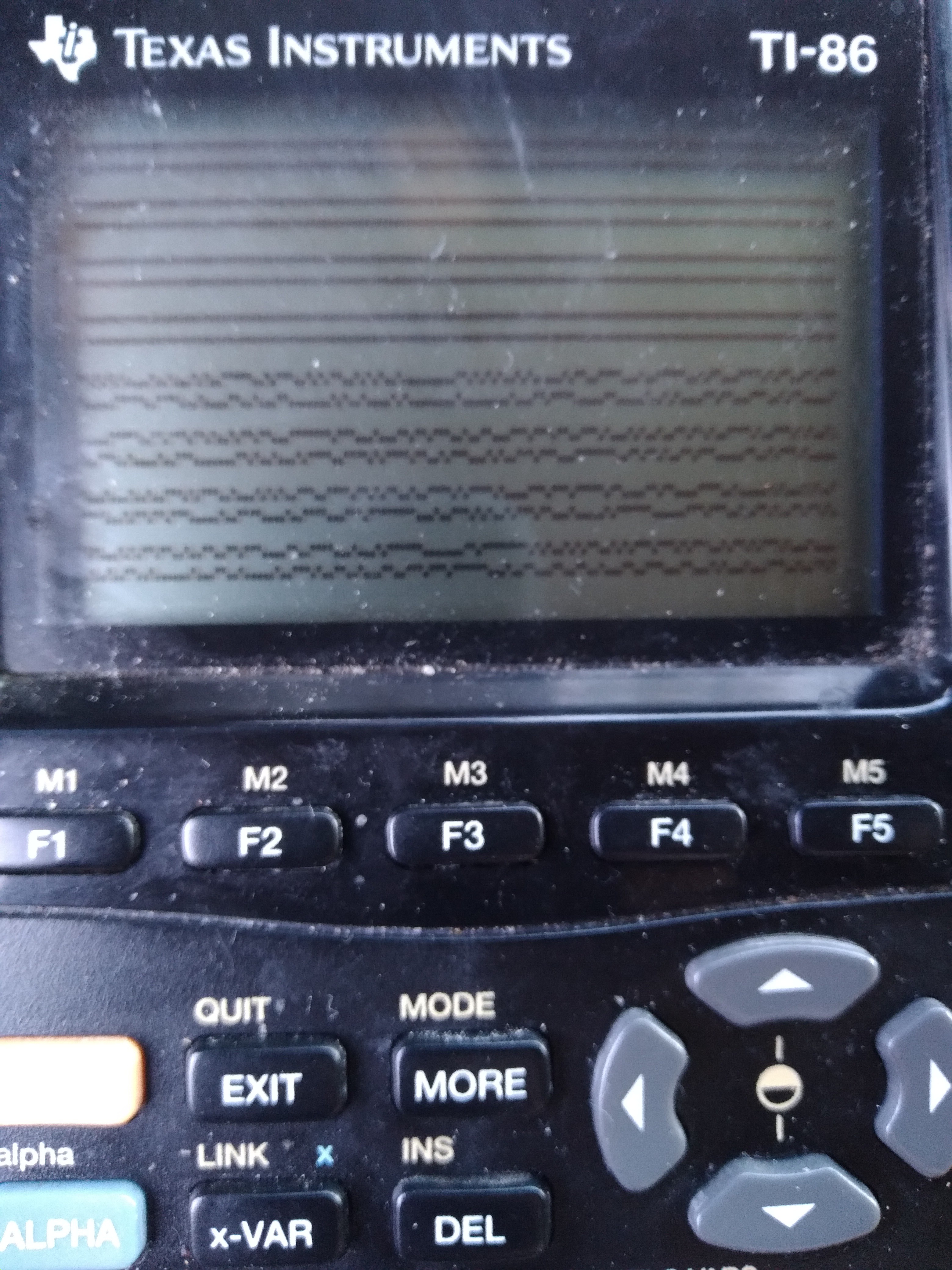
Ok, so it's gnarly-dusty and that's not real sample-data, but here goes:
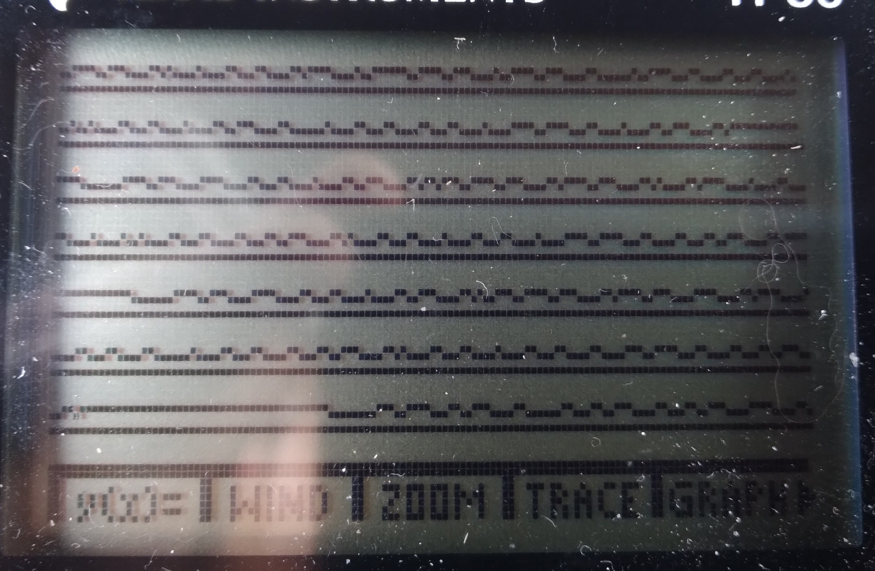
That's two lines of sample-data, from the link-port, wrapping, to show as much as reasonably-viewable (1024x2 Samples visible).
Presently, I think each sample (pixel) is around 6us... that's about as fast as I could code it, with more than 256 samples.
...
I'm planning to view a signal that toggles at a minimum of 8us, so it's going to have some ugly aliasing(? stretching, anyhow)-effects, but I /think/ I can work with it... in post-processing.
.
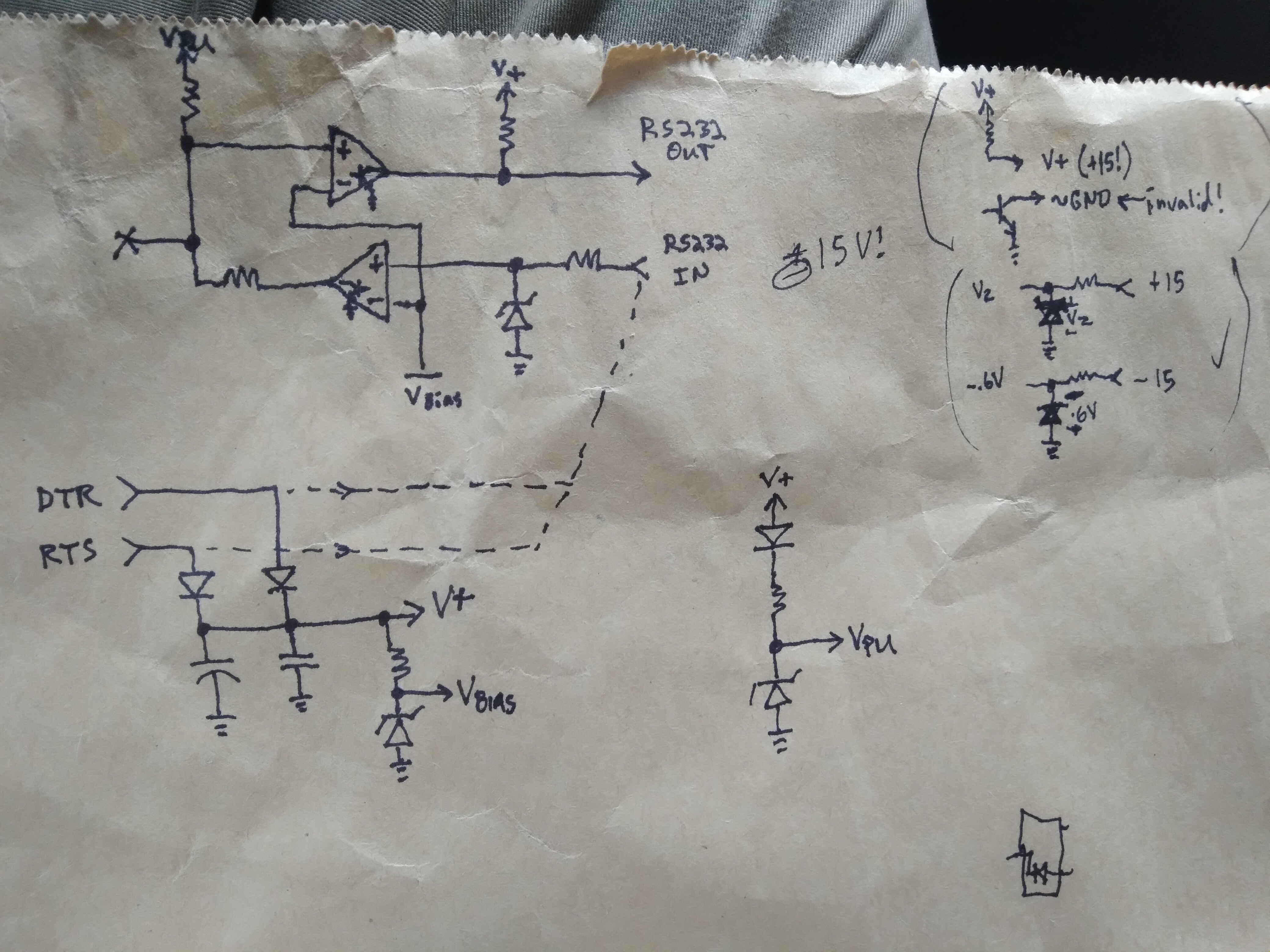
This brings me to the link-cable... I've got the "For Windows Only" graphlink (aka "blacklink") from TI, which is actually quite "dumb", as in it doesn't do anything except level-shifting to make the TI-link protocol work with RS-232 voltages, and vice-versa.
I broke out its schematic a while-back in a past log. https://hackaday.io/project/179772-vintage-z80-palmtop-compy-hackery/log/194140-blacklink-cable-schematic
It's really quite simple, using comparators with open-collector outputs and pull-up resistors in both directions. It doesn't even invert the logic levels (which would've been more per the RS-232 standard, but this is /hardly/ RS-232 compliant, thus "Windows only"), which works in my favor.
![]()
Vbias zener ~=1.6V sets the low<->high threshold for both directions. A pretty decent threshold for most logic-levels.
Vpu zener regulates the TI link to 5V (if available) or drops-out due to the other diode, allowing the calculator to do the pulling-up to closer to 5V (a little gnarly with the voltage-divider between the two TI-Link outputs' pull-not-up-but-to-each-other, better look into that).
Basically, what we have here is a logic level-shifter which is pretty durn easy to interface with various logic levels...
Or, in this case, since my source signal is 5V logic, pretty much matching the TI-86 link port, a handy little isolator... just in case. I mean, it's not /isolated/ per se, but at least it's not feeding my alleged 5V signal (which may well be higher, since I measured ~4.6V with a multimeter while data was flowing) /directly/ into my calculator's CPU.
... handy.
I've [ab]used it a couple times, now, like this...
The prior case was with my UARtoT software... I had (and used) several options, including wiring the link port directly to the 3.3V-level Tx/Rx signals broken-out from my USB-Serial dongle (as opposed to the RS-232-level signals at the DB-9, which are level-shifted by an HIN213, kinda like a MAX232). I was able to get away with that because long ago I added my own zener-regulators to its signals.
BUT. I could've just-as-well used (and did) the blacklink wired to those 3.3V signals, because... the comparators work down to 2V, have open-collector outputs, and diodes prevent things like Vpu being too low from interfering. And, though, if driven at 3.3V, it won't be able to pull up the TI link to 5V, the calculator does that.
So, frankly, it's really quite handy as a general-purpose TI-Link-to-anything level-shifter + 2.5mm three-connector (kinda rare) phone-plug breakout + input/output separator.
And, frankly, it could easily be recreated from common parts... the /least/ common, maybe, being that 2.5mm connector!
.......
Looks like I may also be using it with 7V logic (Wha?!). Gotta get myself a 7V source for that, heh.
.....
I haven't figured out enough of TI-OS to maximize the number of samples; the sampling routine can do up to 64k, but of course, without remapping during sampling, which'd slow it down, the absolute limit is just shy of 48k...
The key factor, of course, is that of reading each sample into its own byte. Memory-wasteful, but computationally fast, for the highest sample rate possible (~140KSps).
So, since I've touched on this rabbithole... Lessee, the z80-VLSI (Toshiba T6A43) doesn't seem to have a means to remap addresses 0xC000-0xFFFF. They're stuck at RAM page 0. I gather that's not just a software limitation. 0x8000-0xBFFF is the remappable "RAM" page. So, obviously, if we can find an empty page of RAM, we could map 16K there. Addresses 0x4000-0x7FFF is the remappable "ROM" page. But, the fact is, for both these remappable pages, anything that's wired to the T6A43's memory bus can be mapped-in to either of these locations. So, if we can find a second empty RAM page, that'd give another 16K. That'd be the 48K absolute limit, since, like RAM page 0 being permanently stuck at the upper 16K, ROM page 0 is stuck at the lower, 0x0000-0x3FFF.
This has all been pretty well-established already.
For some reason, my mind's on the challenge of maximizing this. Not that I necessarily need to.
Would it be possible to /move/ darn-near /everything/ out of RAM page 0, to a temporary location, then use that space as consecutive memory following whatever page is mapped at 0x8000? Why not?
Interrupts-disabled, and careful selection of instructions... No TI-OS ROM calls, No pushing/popping. I think it could. The screen might get garbled (though, it too can be remapped, haven't really looked into those details). Otherwise, why not?
The last bit is the code executing the actual sampling, /and/ a little bit of code to return things back normalish-enough to restore at least the immediately-necessary parts of RAM page 0 (_asm_exec_ram first, maybe)
Hmmm.... nearly 48KB for a program's immediate/consecutive use... (no intermediate remapping)
Of course, doing this requires finding three empty RAM pages... I dunno enough about TI-OS to do this. Though, I did get a brief glimpse at the variable system, and I think I recall they can be up to 64kb(!). So, creating a variable to contain this would have to be within the OS-calls, but accessing it doesn't. I /think/ creating a 64K variable would assure that wherever it starts (surely /not/ at a page-beginning) there would be three consecutive full pages within it, yeah?
Oh, actually, we only need /two/ full consecutive pages, since the third would be temporarily (mapped-consecutively) in RAM page 0... so, a little math /before/ and /after/ sampling (not /during/) and we don't need a variable larger than 48K!
Anyhow...
Other thoughts:
if I'm only doing 1024 samples, (as I am, now) they could go straight to the frame-buffer, then it could be post-processed. Could be kinda interesting to watch that process.
...
What about remapping /during/ sampling?
In order to make samples evenly-spaced, I had to throw in some nops...
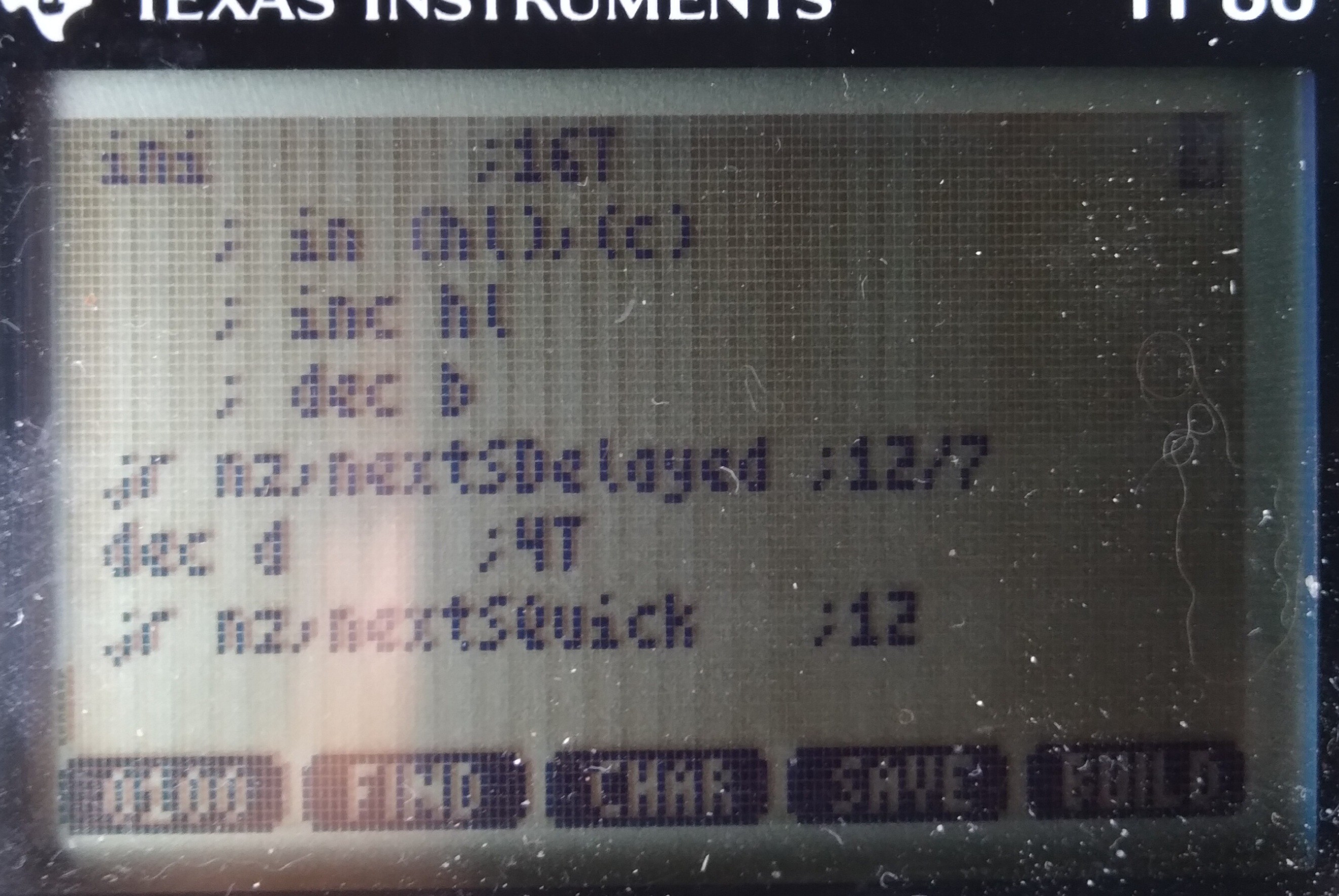
NextSDelayed:
          ;4+7+16+12=39T
 nop       ;4T
 and $ff   ;7T, NOPish
NextSQuick:
          ;16+7+4+12=39T
 ini       ;16T
    ;~= in (hl),(c)
    ;   inc hl
    ;   dec b
 jr nz, nextSDelayed ;12/7T
 dec d     ;4T
 jr nz, nextSQuick   ;12T
But that's 11 unused T-states 255/256 of the time! I wonder if I could throw something in there to be useful... For instance, remapping the "RAM" page is done by simply 'out 6,a'... and I can't see anything wrong with remapping the same mapping repeatedly. So, maybe instead of nop I out6,a... repeatedly. Then, somehow I just need to increment a /once in a while/...
This might be hard to do in 7Tstates, but the idea's there: maybe that unused time could be a bit of a state-machine...
It doesn't matter what order the samples are stored, they can be reordered in post-processing. So, e.g. where the remapping occurs within the sampling doesn't really matter... maybe the remapping occurs (a gets incremented) during the 7th sample after every 16K... then, start hl seven short of the intended destination.... ahh, but wait! hl doesn't wrap at 16k... so maybe we need another state in that state machine to AND h, $3f... and maybe that occurs two samples before the remap/inc a, heh... it could get ugly. But, it's another plausibility to ponder, which I'm sure my brain won't get off for several hours. Even though, realistically, I should only need, oh, roughly 8*3*8*13/6= heh, a measly 416 samples...
Weee!
...
Not so smart: Graphlink as a level-shifter is only one-way for each wire... and, ultimately I'm looking to send data on the same wire. That's OK... just hook up one wire as an input and the other as an output, and we've reverse-Charliplexed one wire to four GPIOs ;)
...
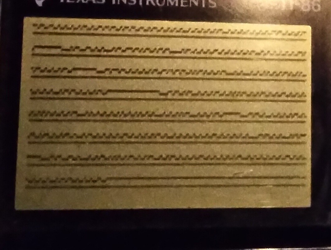
![]()
THIS, however, just doesn't quite look right to me. First-off, it's surely harder to view at 6us samples of 8us data... and that is presuming the calc is actually running near 6MHz... but, there be some long 1's and zeros that don't fit the spec I read. Is it possible the calc is running that slow that it's sampling /slower/ than 8us? Most of it looks about right, though... hmmm...
Further, it's allegedly a protocol that only talks when requested, but clearly that's not the case! It's also alleged (by another source, though only the one) this link /may/ be used for internal communication, while another for request/response... which is prb better, but that one is a different protocol, which means I'd be programming the protocol and requests "bindly." Heh.
And, frankly, I can't figure out what [sub]systems could possibly be intercommunicating via this link... I've looked at many schematics, there's allegedly only one "smart" device in this system, all the sensors I've seen are analog!
Guess I may learn a thing or two...
Or maybe this link is like "dmesg", heh! That'd be /kinda/ awesome, except then I think I'd need a bigger screen, /if/ I could figure out how to decode it.
....
Been working on a screen-cap system so I can analyze at the pixel-level over an extended period without draining the batteries... dunno how, was supposed to be very straightforward, but i managed to crash TI-OS pretty hard, twice!
Anyhow, analyzing that photo again just a second ago, it occurs to me those extended lows look about the same length as those that follow the long highs/idle. The latter are bus-takeover-requests, the highs being idle. The former, then, similarly-lengthed-lows /without/ a prior idle might just be an immediate response from a previously-non-sending device.
That makes a lot of sense.
-
MWAHAHA!
08/26/2021 at 17:56 • 0 commentsI /finally/ figured out /exactly/ the reason I took on this project... it's a major component of another project I'd backburnered so far as to only have the vague recollection of its needs, and to nab it when I found it.
Along the way, easily two years, now, I thought of many potential solutions, saw many others on HaD, found a few /almost/ solutions at Goodwill, including a few "JuiceBox" toys, which probably would've worked, but not ideally...
If this was my prior "normal" life"style", it'd've been probably one of two options: either build something with an AVR and scavenged-parts, or just use a friggin' laptop. But both these options are pretty difficult in this life"style."
A couple years back I was living on my uncle's farm... he had a blutooth doodad which would make a phone again /almost/ perfect... but the app was far too limited, and the affordable ones apparently haven't been hacked-enough for better to exist, nor protocol documentation... and, again, in this environment coding [learning to!] Android apps isn't really feasible...
No, what I needed was a low power, small, computer with a couple 5V GPIOs that I could develop the software /on/.
And here I finally have one... three, in fact, and mighta wound-up with a fourth if I didn't calm myself down upon seeing it for $7... And I've been far more than "dinking around" on this thing for /months/ without its even once, until waking this morning, occurring to me /why/.
HAH.
Nevermind the many-times-daily reminders. Nevermind even having written about a probably-more-important project I'd been neglecting. I had two, two was thrown at me... but I guess I forgot to put them together.
Heh.
-
"FTDI"-type USB-Serial link?
08/26/2021 at 00:47 • 0 commentsNow, it seems, rather than working on my FLASH backup software (which was an offshoot/tangent of my original project goals, and which also got offshot for several weeks), I've become somewhat fixated on the idea of a new "homebrew" graphlink, using one of the many now-commonly-available USB-to-Logic-Level-Serial-RxTx adapters, e.g. the "FTDI" built-in to most arduinos...
Personally, I'm rather fond of the PL2303, And I built my college research project with a CP2101 (as I recall), Though, an FT232, etc, would also do the job, /sans/ the RS232 level converter found in retail USB-RS232 converters... I'm talking about the little boards I'm almost certain are a few bucks from sparkfun or adafruit, these days.
...
The idea is: wire-up the Tx to the "white wire" and Rx to the red. Maybe add a pull-up resistor. Ground, of course. And bam you've got yourself a $5 USB graphlink that works with TILP.
But, this isn't an easy task, making this possible.
... Though, it's mostly software, which most folk would never see the inner workings of.
So, here's an overview of the inner-workings, starting with an "It's not /that/ easy, even for the end-user"
The thing is, the TI linking protocol, at the lowest level, is not /at all/ compatible with Asynchronous Serial of the sort coming from such USB converters, (or a real serial port with a MAX232-like level-shifter, if you'd prefer).
So, this creates a chicken-egg problem. If you want such a simple/affordable/ubiquitous interface between your calculator and your computer, you've got to teach the calculator how to communicate with it.
If this were the era of my middle/high school years, that'd simply mean asking Bobby in Math Class to download the utility from his calculator. But, I get the impression TI-8x "sneaker-net" isn't nearly so common these days. So, you could download the utility off the internet, but how would you transfer it to the calculator, when you need that utility on the calculator to download the utility from the computer onto the calculator?
Right. So, for the user, it wouldn't be /exceptionally/ difficult...
The TI-86 allows you to enter custom programs by-hand in hex-code.
Get a calculator from Goodwill, grab the "FTDI" you've already got in your drawer, type in some hex, load up TILP, select "upload AsyncLinkUtility" then, thereafter, it just works.
.
Now, forgetting for a moment how much friggin' work it would be to make it that simple for the user...
I gotta wonder how much is reasonable to expect of them.
So far, it seems, it'd be about 32 hex-codes that have to be hand-entered (in hex, 64 characters) just to create /a container/ for the utility which will later be uploaded.
OK, then we need /more/ hex values for the calculator to understand the bytes coming in from the computer's Tx line... I'm guessing also somewhere around 32 bytes to be hand-entered.
I /think/ it could be done about that small... about 128 characters to be typed, and 64 spaces. Typed /correctly/ mind-you!
I dunno, that seems like a lot when there are other options from the parts-drawer. OTOH, those other options are also lacking in many ways.
Also, as far as I know, the TI-86 is the only one which /can/ run hand-entered applications. So, this'd be useless for TI-85's, 83's, etc. (Lacking sneaker-net).
...
Another option is just to throw a microcontroller inbetween. And, in this era of arduinos and such, that's not a huge ordeal--for someone proficient-enough to wire-up an "FTDI"--to wire-up and program. Maybe even less-so than hand-entering the upload utility. The microcontroller speaks native TI linking protocol on one side, and Async Serial on the other (maybe even acts as a USB-CDC serial converter).
This option, really, is /way/ better, in a lot of ways. E.G. it wouldn't interfere with normal linking with other calcs, and it doesn't require special utilities on the calc. But, not everyone has /the/ arduino sitting in their drawer... whereas, I think they'd be more likely to have an "FTDI" of any manufacturer.
...
So, realistically, the "FTDI" route is a bit niche, maybe, and would be a LOT of work... it probably doesn't make sense.
But, that's where the brain is at these past several days.
I think it can be done. I think it can even be done without need for level shifters from 6V to 3.3V logic.
I keep convincing myself it's a fool's errand, yet keep getting new ideas that I have to look into. The latest being: how much code would it take to upload the full utility into a TI-OS "program" container/variable... about 32 bytes, minus the actual communication.
Doable.
...
FYI, regarding 3.3V logic levels: the TI-86 has a diode after the 6V pull-up resistor on its "input". The input can be turned into an output. Driving that side of the diode low would effectively remove the 6V pull-up from the wire. Thus, using that wire as essentially an open-collector /output/, a 3.3V pull-up resistor can be added to the 3.3V ["FTDI" or microcontroller] input (if it doesn't already have one).
That leaves, then, the /input/ wire, Rx on the calculator, wired to the 3.3V Tx output from the "FTDI"... this is where the concern lies, despite its seeming backwards to worry about a low-voltage output driving the input of higher-voltage logic. The problem is the 6V pull-up resistor can't be disabled in this case, so that resistor /could/ send current into the 3.3V output, when it's driving high. When driving low it's not a concern, the low-side output transistor is designed to take current in. When driving high, though... it's designed to put current out. Most likely it won't be an issue, that current would be tiny... it might feed back into the positive rail, some circuitry might get 3.4V instead of 3.3... it might be fine. OTOH, it could be a problem. Being an /output/, it may not even allow reverse current. And then there'd be 6V on your 3.3V-rated pin.
Anyhow, I dig the ability to disable the pull-up...
....
And, yahknow, I've convinced myself again this is a "fool's errand," isn't at all necessary for my goals for this project, probably wouldn't be made use of by many, would require a tremendous amount of coding in things I still know little about, so on... yet can already barely resist thinking about how to achieve it. Heh!
-
What Next?
08/21/2021 at 18:15 • 0 commentswell, now that I've FINALLY backed-up that FLASH, I guess I should start working on the stuff to actually /use/ it!
Which, too, isn't really what this project was about... another tangent or branch in the fractal that is this project... to /enable/ this project. Zooming out to get the whole picture... I can't really seem to do. But, having finished the last part, at least I can zoom out a little.
OK, so I added the FLASH chip months(?) ago so that I could do quick nonvolatile backups of my progress with this project... a place to permanently store source code, libraries, executables, etc. Especially for those moments when I'm about to try some code or hardware modification that might wipe the memory...
The irony, I guess, is that I wound-up doing /most/ of that stuff /while/ trying to backup the flash to eventually enable my doing /of/ that stuff. Heh.
...
And, now, I don't really have many ideas of what else I wanted to do like that. Heh!
...
Software-wise, there was some discussion about writing a custom OS, or at least some bare-metal code that could boot the system separately from TI-OS... basically dual-boot the thing. But, again, I don't really know what to /do/ with that!
That idea, though, extended to my full-RAM-backup-to-FLASH idea might make restores easier... hmm. Backup from within TI-OS, then if "memory cleared" flip a switch to boot from flash, wherein the memory would be restored and plausibly TI-OS could be given back control (flipping that switch back, or maybe toggling a flip-flop) as though it'd never been not running...
But... again, heh... this wasn't the project, just an enabler!
...
Other ideas, well... at one point I thought maybe it'd make for a handy UI for other projects, e.g. a dumb terminal for an arduino or maybe even a linux box... but, really... small screen, weird keyboard... A SmartResponse would be smarter. And, besides, why add an arduino when what we've got here is a full-fledged computer?
OTOH, maybe I'm not thinking about this right... if I thought about this TI-86 as a (MY) friggin' calculator (since my trusty TI-82 I've had since middleschool was somewhat poorly hacked with a backlight that causes memory-clears), yahknow, a tool instead of as a thing to be hacked, maybe it'd be a bit more like a piece of test-equipment. Then, a dumb-terminal already at my side could be quite handy. Hmmm.
...
In a similar vein, I've somewhat pondered connecting #sdramThingZero - 133MS/s 32-bit Logic Analyzer to it... kinda goofy, in this era, but a huge part of that project was the goal of its being inerfaceable with even old compies of this vintage via parallel port.
...
In other realms, well... For some reason I've felt the urge to connect up some old ISA cards, CGA, VGA, Soundblaster... I really have no idea why, though... just to make this a computer, I guess.
In other other realms... well... blinking LEDs is doable with a shiftregister on the link port... that's just software, hack-wise.
Adding a PS2 keyboard to the link port shouldn't be too difficult, especially having seen the 200Hz interrupt handler can call a user-function. I think someone already did that. Even a PS2 mouse, as I recall (huh, how would that work with the OS?)
So, I suppose that was part of my interest in seeing about other I/O options than the link port, because a serial port, mouse, and keyboard can't all be connected at once, eh?
Heh.
Oh, I got a for-parts Palm Vx for less than $10... was kinda thinking about /maybe/ hacking its backlight into this calculator... and now it occurs maybe the touchscreen is also possible.
...
Oh, and some thoughts of hooking up #The Artist--Printze...
But, really... I dunno what I'm going for with all this... and after finishing the FLASH backup /finally/ instead of elation, I've mostly felt like most of my projects are little more than a waste of time.
This past month my poor van has been trying to tell me she needs some lovin'... and believe me, she deserves far better than I give her... But I'm nowhere near as good at that stuff, and you saw how a three-hour project, in a realm I know a bit about, turned into WEEKS. Imagine something like that happening with engine parts strewn about. Now imagine that with those parts strewn about a car-parts-store's parking lot for weeks. Heh. Oh, nevermind the fact the calculator-project cost like $20, total... would that even cover spark plugs? Poor Vanna keeps taking one for the team.
-
UARtoT Functions -Flash Transferred
08/21/2021 at 04:39 • 22 commentsBrief recap:
The ultimate goal of this project was long long burried under tangent after tangent that each seemed almost certain to take only a few hours at most, and wound-up taking weeks, instead.
I piggy-backed a 256K FLASH chip on the TI-86's OTP ROM what must've been months ago for the sake of being able to run full system backups while I was doing gnarly testing of hardware/software ideas that could easily result in "Memory Cleared" on countless occasions... which would be quite a setback, since I'm writing the software /on/ the calculator...
Yes, I understand I could back it up regularly to a computer. That's another story. But, sufficed to say that's what I've been doing for backups these past weeks, instead of backing up to the flash, which is already installed and functioning.
Why?
Because I found that chip in my long-ago-scavenged sorted-parts bin, and realized that over the past few years I've dug out old PCBs that'd been scavenged and realized many times that I might like to get some of them functional again someday. So, somewhere in there is one missing its firmware... and this chip might contain it.
So, no idea /what/ it came from, I decided to dedicate a few /hours/ to backing up its contents.
Three (more?) WEEKS later, it's /finally/ done.
What's it from? Apparently it's the BIOS from a Compaq Presario... which, frankly, even if it's from my once-beloved P150 laptop (as opposed to, say, some random desktop someone passed onto me), I certainly wouldn't've gone to all that effort for it... (Oddly, I don't see many strings in there at all... basically just "Phoenix BIOS" and "Compaq Presario"... what about all the settings /in/ the BIOS Setup program?!)
OTOH, in the process I managed to give the TI-86 a new trick... it can now transmit RS-232-compatible serial data through the "Windows Only" "blacklink" graph-link cable, which was originally designed to be bit-banged from Windows via the handshaking lines.
Yep, that's right... My TI-86 has UART capability, now... and it was "only" a matter of rewiring the blacklink's DB-9 through a passive adapter and a little software.
OK, not quite... The TI-86 doesn't seem to have a high-speed counter/timer/clock accessible via software. The only thing like that is an interrupt about 200 times a second... and, I'm not too interested in 200Baud communication. So, really, not being a z80 wiz, bitbanging asynchronous serial frames would be quite difficult.
I actually spent quite a bit of time near-certain there must be a higher-speed counter accessible /somewhere/, and dug all around the ports, for many days, to no avail...
Then a moment of clarity... Hey, I need a clock, why not use the computer as the clock?
So, now, the computer transmits 0x55, which results in 10 alternating bits (including start and stop) and the calculator looks for those edges and transmits its own serial frames/bytes synchronized to those edges.
I have this weird feeling I have, yet also haven't, heard of this before. I mean, it's so friggin' simple, surely others have done this... but, I can't at all think of /where/ I might've heard of it.
Regardless, it /does/ work, and surprisingly well. I transferred all 256KB of the Flash twice without a single bit error. 4800baud was more than fine for my needs. But that speed-choice was a remnant of something else, by no means the limit. Interesting side-effect of this technique, the other device doesn't care what the computer's baudrate is, as long as it has enough processing time. Kinda groovy.
So, I call it a UARtoT. Receive 0x55, Transmit whatever you want. Unidirectional, but that's all I needed.
...
Ugh... now why did something /so/ simple throw me off-course for WEEKS?!
Lemme put it this way:
DO NOT ATTEMPT TO PROCESS BINARY DATA WITH BASH.
NO! You CANNOT store every possible combination of 8 bits in a bash variable. No. Don't even try it. Even if you think you've found "the trick" I assure you you've only found one workaround for only one of the tricks bash has up /its/ sleeve. I doubt it's even possible, but /if/ somehow you managed to get every byte value storable in a bash variable, then surely you haven't considered every /two-byte/ combination... "But, what? I'm only reading ONE byte at a time!" HAH HAH HAH! That's what YOU think!
Convert it to a two-byte string, hex, seriously, using hexdump and redirection.
Seriously, DO NOT take the above as some sort of challenge, like I foolishly did. I didn't have the luxury of someone's saying it wasn't possible. I'm Trying To Save You DAYS Of Futile Aggravation.
Surely there were other reasons this took so long...
Oh yeah, stty is /barely/ comprehensible, but also has a tremendous impact on binary data.
Oddly, the code I wrote-up in assembly, of all languages I know near ziltch about, apparently worked perfectly all along, from the start. Hah!
...
I'm sure there was /plenty/ more that turned my three hour tour into weeks, it's probably rambled-about in past logs. This was all supposed to be a brief explanation about the joy of FINALLY having this part of the project (which was never really /part/ of "The Project") finished so I can actually get to the parts I'd originally had in mind...
Now, what were those?
I suppose some of this helps that stuff, anyhow... all sorts of new libraries... lots of new details about the calc's hardware and hackability...
It really hasn't at all sunken in that I've finally reached some huge milestone.
..
Surely I shoulda been calling it UARtoST...
-
FRIGGIN DAYS
08/19/2021 at 00:36 • 5 commentswhile [ 1 ]
do
read -n 1 byte < /dev/ttyUSB0
...
done
SHOULD BE
while [ 1 ]
do
read -n 1 byte
...
done < /dev/ttyUSB0
FRIGGIN DAYS
...
Friggin code worked great. Friggin blacklink powered fine. Friggin weird voltages on PL2303 and HIN213 work fine. Friggin inverted-logic for RS-232 levels worked fine. Friggin bypassing RS232 levels worked fine. Friggin current-draw from a handshake line worked fine. Friggin 5V source creating 2.5V highs right at the HIN213' threshold worked fine. Friggin 8V battery worked fine. I'm sure I'm forgetting a friggin lot of friggin things I friggin tried.
Friggin 9600baud worked fine. Friggin 300 baud worked fine. Friggin 19200 baud had one measly bit error. Looks like the only test i tried that wouldn't've worked was 75 baud.
Put the friggin' pipe on the friggin' while loop, not on friggin read.
...
This explains it pretty clearly /for a file/: https://stackoverflow.com/questions/58829941/i-o-redirection-in-a-while-loop
And, I think, were I writing it for a file, I'd've thought of it like that... I've certainly, in the past /written/ it like that, for files and strings, using the <<< redirector...
So why would I've expected differently with a serial port? The device node is designed to look like a file. Heh!
Now, I guess, this again is where stty might play a role... and maybe IFS?
Unlike a file, the serial port device node isn't static. If you read the first byte in that "file" it will be different each time. Right? And you can't exactly seek the twentieth byte, then go back and seek the first. Right?
So, I guess, I thought the serial port was different.
But, now that I think about it, redirection of stdin is a bit more like reading a serial port than reading a file... stdin isn't seekable, either. Right?
Maybe, maybe, you could treat a "line" as seekable, as though each /line/ is a temporary file... but, mostly, one reads that entire line in one go, then processes its bytes/words/whatever afterwards.
So, again, I guess this may be where stty and IFS may play a role. When one accesses stdin for a read, or redirects a file or serial port to stdin for a read, what exactly happens?
A normal 'read' call would halt the script while the user typed... until they hit Enter, (IFS, right?). Then the 'read' would be solely responsible for processing /all/ of what the user typed in that time. Another call to 'read', then, wouldn't process whatever was left-over from the last read, it would wait for an entirely new line to be entered.
So, probably, with default stty settings on a serial port, it would do the same. Duh.
It gets confusing with read -n1, because, now I recall doing similar in the past, it doesn't follow its normal rules.
Normally read reads each word (separated by space) into each variable name supplied, e.g:
$ read var1 var2 var3
Will store three sequential words into the three variables. BUT, it says it /also/ stores anything remaining in the last var... So, if you enter four words, var3 will contain the third AND fourth words.
OK. So better to write it:
$ read var1 var2 var3 varExcess
And, just don't use varExcess if you don't care.
Now, logically, from that explanation, say we just wanted to grab one byte:
$ read -n1 char1 excess
Sould put the first byte into char1, and any remaining bytes (up to Enter, per IFS, right?) into excess...
But, I don't see that happening. The variable 'excess' is always empty.
Maybe it's to do with my initial testing, which only sent one character every half-second... But, per default stty settings, it should've waited at that read until it received Enter... which, of course, my test never sent. BUT it /didn't/ wait for Enter, or else it'd've never finished that first 'read' and would've appeared frozen.
So /somewhere/ it was sorta set up the way I intended... so, then, it would seem maybe an stty setting told 'read' it was done whenever the buffer was empty. Then, read should've thrown whatever it got after that first byte into 'excess'. But, again, it didn't. At least in that test, which may well've been the result of sending characters so slowly that the entire buffer was read each time, containing only one character each time.
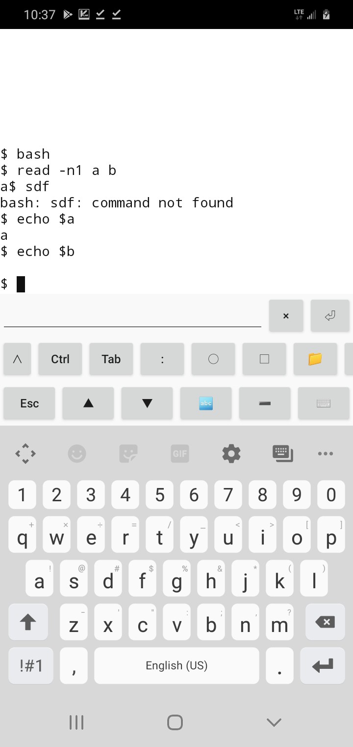
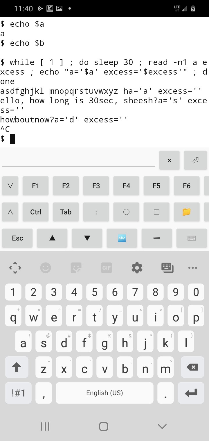
(Wherein, I'm working on past memories, vague recollections of having used '-n1' and having similar results even with stdin, excess was always empty, right? I really should do a real test of this theory... but... not... right... now... hey wait! I'm thumbtyping on a friggin supercomputer, it even runs bash! BRB. (Reminder to self, hard-learned: superThumbCompy does /not/ reliably store text entry in websites when switching tabs or apps)
![]()
How friggin cool is that? (BTW, the trick is, install droidVIM, then ':sh')
so... it looks like I was right... top that off, it actually exits immediately after getting that byte, didn't even wait for enter.
So, then... I dunno what to think. Seems to me it's a design-flaw to empty the entire buffer when only one character is read from it. And, the manpage doesn't explain it, either.
So, now, which buffer are we talking about, here? The serial port chip has its own buffer. A "real" serial port would be readable by the driver one byte at a time, if the driver implemented it. But, it's somewhat logical to think there's really no reason, in these days of huge RAMs, for the driver/OS /not/ to grab everything in that buffer, to be stored in an OS/driver-side buffer. In fact, it's entirely likely the driver does-so periodically in the background /regardless/ of whether any software (i.e. 'read') requests data from the port... wherein, almost certainly, the driver and/or [and even more likely] the OS has yet another buffer... this one likely still containing raw data... not processed into "words" nor split up into "lines", nor even yet manipulated by stty settings (e.g. converting an input NewLine byte into BOTH a NewLine AND CarriageReturn). In fact, my guess is that stuff is handled during the software's request for data from that buffer.
Now, 'read' requested a single byte from that device-node. I can buy that it got it through some sort of stty-process to convert newlines, etc. I can buy that BASH wants to do its own processing of it (e.g. word-splitting, looking for IFS, etc.). Yet, in that quick-test (screenshot) bash clearly only requested one byte from stdin before exitting 'read'... AND it didn't fill in the excess to variable b, as the manpage would have me believe, if it'd instead asked for (or otherwise expects it might receive) a 'line' (i.e. the buffer contents)... so, somewhere, it would seem, buffer data is being flat-out discarded. That... doesn't... seem... right... for nearly /any/ purpose... without being explicitly told to do-so, or explicitly explained in a manpage.
Now, somewhere therein, one might suggest that, well, say some talkative serial device was always talking to the serial port, regardless of whether the software to read it was ever even executed... should that buffer be 100MB?
I suppose it's an important question...
What /should/ happen in that case? Every time the 'file' is closed, it clears the buffer? Only begins filling it if the 'file' is open? Hmmm...
I /suppose/ therein lies the answer... it's not that bash did anything unusual in reading the entire buffer, then discarding the 'excess' despite the manpage saying, essentially, that the rest would be stored in the last variable... i guess the wording should be clear from the description of -n1 that only one byte is grabbed, and the excess isn't even looked-at... That's preferable, anyhow, else even my second test wouldn't've worked and we'd need a second nested while loop to process the excess from the buffer-grab during that first read.
Fine.
So now it's back to the OS, wherein the port's 'file' was opened... and now we have to presume the OS-side buffer was empty, initially, upon opening the 'file', right? But the port chip's buffer /probably/ contains data, much of which has been lost, since its buffer isn't huge... so then we've got to wonder... does opening the port 'file' for read /first/ clear that buffer? Kinda makes sense it would... OTOH, there's really no way of knowing whether /during/ that clearing process a valid byte is coming in... anyhow, fine, that's up to synchronization ala handshaking, or packet headers, etc. And, lacking those, (as in my case) loss of data during that time should probably be expected.
Fine. Open port, lose some data from before it was open, maybe lose some data while it's opening... but now the buffer is ready to go, and no more data should be lost until that port's closed, which, of course, happens immediately after 'read' gets its one byte. OK.
The buffering is only active when the port is open. Bam. So, open it for the /entire/ while-loop, not /just/ during the read... bam.
And the reason it seems different in my screenshot is because 'read' didn't open stdin, it was /already/ open by bash. And 'read' didn't close stdin, bash just took it back... /exactly/ like the while loop would, after 'read' when stdin was redirected for the entirety of the while loop, instead of just for read.
OK.
Buffers disabled/cleared unless/until port is open.
Sheesh.
A bit like typing on the keyboard while the computer is off.
Gotcha.
Turning it on for a moment, waiting for one keystroke, displaying it, then turning it off again...
OK... I GET IT!
Nope... nope I don't...
If it was stdin... and it was a while loop... and there was a sleep of 30 seconds before 'read'... and someone typed during those 30 seconds... then 'read' would get the first byte typed during those 30 seconds, right?
BRB...
![]()
(How cool is that? And I once thought "smart phones" to be little more than dumb toys)
Right... so, stdin was already open... nothing grabbed the data (except screen printout, which I guess is another matter entirely) until the read. Read grabbed a byte from the beginning of the buffer. Makes sense.
But, no... no it doesn't...
Oy... I could go into why, but... I've gone this far, and the end result is the same... this be how it werkz, so figure out how to remember it: buffer is only buffered when the port 'file' is open, cleared otherwise. Bam.
-
Tl;dr thus far...
08/17/2021 at 18:49 • 0 commentsThe TI-86 is very hacker-friendly...
Aside from being designed with users' custom assembly/machine-code/binary-executables in mind, there are also quite a few openings for hardware-hacks.
I did some testing and discovered that there are 20 accessible address-bits and 4 additional Chip-Selects, only two of which are used (/CS0 for ROM, /CS1 for RAM). That makes for 4MB of address-space, the vast majority of which is unused, thus availaible for other things, memory, flash, mem-mapped I/O, etc.
Port5/6 select how/where to map this into the 32k of mappable z80 address-space. There's really nothing complicated about the bit-layout of these ports, it's simply address-bits A21-A14, wherein A21-20 are decoded/demultiplexed onto the four chip-select pins on the Toshiba T6A43 Z80 VLSI. Which, BTW, is also used in the TI-81 and TI-85.
The TI-86 appears to have been designed for FLASH where the OTP ROM is most-often located, instead. This required a bit of hackery on TI's part, because apparently the T6A43 doesn't supply the standard /Output-Enable memory bus signal, and, instead, usually they just tie it active on the ROM and RAM and allow the Chip-Select and /Write-Enable to do the dirty-work. Flash, however, apparently often uses /OE disabled to put it in programming-mode. Thus, from the looks of the board-layout and pads for unpopulated/shorted "Switches" (and U10, as I recall), they used /CS3 and a GPIO (which I've yet to figure out) to access the FLASH, usually at /CS0, for writing.
From the looks of the Design/Assembly (manufacture, not software)/TI-OS, it would seem they didn't intend to use FLASH in the user-end-product, just for development purposes.
I have hacked-in my own FLASH chip on /CS3, piggybacking it atop the ROM. There is /plenty/ of physical space to do-so, under the LCD board, almost making me wonder if they had that in mind when designing it. As I said, this guy is very hack-friendly, and much of that appears to have been by-design. Go Texas Instruments!
For /OE, I just used a high address-bit. Thus, for reading my FLASH it's accessed by mapping /CS3 and selecting 16k of the 256k in Port5 or 6... For writing, /OE=disabled=high, the same is done, but now the same 16k is selected between the range of 256k to 512k.
My software for actually /using/ that flash, thus far, is /very/ minimal, just a test-program to write a few bytes, and another to read.
Using it /within/ TI-OS, as opposed to within my own dedicated programs, is a long-shot... mostly because I just don't know enough about the OS to know what's possible.
Though, much to my surprise, it would seem TI-OS /does/ in fact provide /many/ opportunities for user-addons, akin to DOS's old TSRs (Terminate and Stay Resident, applications that run in the background, e.g. hardware drivers, screensavers, etc.). @ziggurat29 discovered and described to me one of these in the timer-interrupt, wherein a user function can be called 200 times a second.
So, it /may/ be entirely plausible to add support for this add-on FLASH chip into the OS, e.g. for storing programs, or whatnot, and accessing them in normal ways. I dunno.
My intention with it was/is to merely create a backup/restore program which will simply copy the RAM, byte-for-byte, so I don't lose my hard work writing assembly-programs when I do something stupid like pop the stack too many times or forget a return. But, it could surely be used for more. (There's some discussion about maybe writing my own bare-metal code, and flipping a switch to select the FLASH from /CS0, making it bootable. We'll see).
Speaking of writing assembly... ZAC, is a Z80 Assembler/Compiler that runs /on/ the TI-86... Very Handy. It also comes with Asmide86, which is a great text-editor and IDE that works with ZAC. So, you can write assembly /on/ the machine you intend to use it on... then slide it in your pocket. It also has some features to recover from stupid mistakes, which has saved me from many a "Memory Cleared." Amazing work, Clem Vassuer, et. al.
There are, of course, other methods for writing programs on a "real computer," then uploading them to the calculator, if, yahknow, you prefer C, or are a touch-typist, or prefer 80 columns or more... but I haven't looked into those, yet. SDCC may be in my future, as assembly is not my native language, especially on CISC (HOLY CRUD there are a TON of /weird/ instructions! How on earth can C, or anyone, keep track of them?!) But, for now, thumbtyping assembly is where it's at... and it's pretty durn amazing what I've gotten out of it and 4 AAA batteries.
...
Presently I'm working on a RS-232 compatible means of dumping data from the calculator to a computer... the reason is goofy (I found my FLASH chip in a scavenged-parts bin, and may someday find that the PCB it came from could've been useful if I hadn't scrapped its firmware).
The /other/ reasoning is also goofy... I have the ol' "blacklink" cable, from back in middleschool, to link it to my computer. This guy is "For Windows Only" which really means that it's not really RS-232-compatible, but happens to work with the serial hardware that was available in most Windows-PCs at the time. Aka, cheap. Most computers these days, including mine, don't have real serial ports anymore... so, technically, this "black link" graph-link cable is really not at all supported these days.
"Tilp" the open-source TI-Linking-Program is also extremely handy. ('apt-get tilp' Nice job, guys! Thankya! Apologies, your names aren't in my view every day).
However, it doesn't support this cable through a USB-to-serial adapter... but, since it's open-source, I was able to hack it to work... and, now I see /why/ support for this method isn't at all a priority. Simply, the blacklink is bit-banged, it doesn't use Tx/Rx. USB packets are huge, say 256 bytes, each, just to toggle one wire. I mathed it and found that 1.5Mbps USB, running full-tilt, can only bitbang the graphlink protocol via those pins at about 100bytes per second. Also, since the blacklink uses nonstandard signal levels and gets its power from the signals, some USB dongles just may not work with it at all. Get yerself a different cable if USB is your only option!
That said, it works in my case, and 20min for a backup isn't /horrible/.
So, I want to backup this FLASH chip before I overwrite it, and I thought I could bitbang RS-232-compatible serial frames in the calculator much faster than 100Bytes/sec... throw in a DB-9 adapter to reroute the data lines... go!
Wherein, one thing many-a-hardware-hacker might find an annoyance at its lacking: It doesn't seem there's a timer besides the one used for interrupts 200 times a second. Far too slow for timing bits to be banged at 9600+ baud.
My solution: the computer transmits 0xAA (or is it 0x55?) such that each serial frame sent by the computer looks like alternating 1's and 0's. Thus, the computer acts as a clock for the calculator's data transmission.
(Erm... now that I think about it, 9600 bps at 10bits per frame... oh, right, 960bytes/sec, whew! Thought all this effort mighta resulted in 96bytes/sec!)
Anyhow, it works at 19200baud, but only in short bursts, which I think is the result of the blacklink's using nonstandard signal levels and drawing its power from the signals. I'd hoped it'd've been simply a matter of a DB-9 adaptor and a little software, that it could be useful to others without much custom circuitry, but it looks like it may be a little more effort. OTOH, USB to TTL-level serial adapters are pretty common these days, what with Arduinos, so maybe this is a good thing... graphlinks are probably far scarcer! Heck, I might even be able to wire it up straight to the 3-pin phone-jack... hmmm...
BUT: So far, this is /one/ way communication, calculator to computer. I dunno if it's really feasible to send data from the computer to the calculator this way... I don't have a high-speed timer to work with!
...AND... this, really, was supposed to be "a three-hour tour"... just a quick day-hack to backup that FLASH... instead, we're on week three, I think.
Though, I suppose, auto-baud with cycle-counting of varying-length machine-language instructions /could/ be an interesting challenge... /THAT/ I imagine to be a weeks-long endeavor, and judging by the way things've gone probably means it'd take months, HAH! /maybe/... we'll see...
And, again, I don't know enough about TI-OS to know whether this could be injected to replace the normal linking protocol... so it might be limited in its use to custom programs, as opposed to, say, another means to connect to tilp. (And, again, it would be necessary to upload the TI-OS-injector program in the first place, which makes it a bit of a chicken/egg problem).
On /that/ note, another amazingly-hacker-friendly feature of the TI-86 is the ability to load assembly programs /by hand/ by typing in the hex values of the z80 opcodes, then executing them. Very cool.
But, a program like this, hah, hundreds upon hundreds of hex values, I think.
...
Lemme think, am I forgetting anything?
I've done a lot of looking into other means of hacking in new hardware, e.g. by tapping into the LCD, but all those are pretty much moot since I discovered /CS2 and /CS3.
I also had a goofy idea of adding a higher-precision timer/counter via the 200Hz timer, which I think might merely be an RC oscillator... by tapping an ADC to that oscillator. I kinda like that idea from a "shits-n-giggles" standpoint. Though, frankly, I think that really amounts to a much faster RC oscillator, judging by the t=RC best-guesses I see on board, fed to an internal counter/divider which just isn't accessible. So, then, a TTL 8-bit counter would be easier to tack on, and far more precise.
... and, again, there's actually plenty of room inside the case for a few extra chips deadbugged here and there. Wee!
...
Ahh, yes, then a few ideas for a custom/homebrew computer, plausibly z80-based...
One regarding the memory-remapping circuitry.
First, an aside: TI-OS has functions for "absolute addressing" or "24-bit addressing" using register A for the third address-byte in the typical z80 scheme of using the 16-bit HL register for memory-addressing. I did some digging and found that those functions I looked at /don't/ use AHL to address the actual T6A43 address-wires directly. The AHL addressing scheme is /very/ OS-specific, and from what I can tell doesn't even give full access to the ROM, only the RAM. The AHL scheme is very much software, not really hardware. And, it does what it does by remapping... (so, e.g. you may have to remember to remap /back/, when you're done with those functions).
That said, before I figured that out I thought maybe those functions used a third mapping-port... one which is only used for /one/ instruction-cycle. And, I think I figured out how to implement something like that with a standard z80 with little more than a couple flip-flops for timing and an 8-bit latch for the higher address bit.
Why would something like this be useful? Say you've got a huge circular(?) buffer that isn't accessed very often. A byte comes in, throw it in the buffer, continue on with whatever else you were doing in your /normal/ memory-mapping without having to remember to remap it back.
I thought it was a groovy idea, anyhow...
Then, yesterday I was on a reading-binge and looked up the z80 on Wikipedia, and it turns out something almost exactly like that is used for accessing the IX and IY registers. The z80 design apparently is an extension of the 8080 which is an extension of the 8008, if I've got my numbers right. So, IX and IY didn't exist in a previous architecture, but HL did. So, in order to access IX and IY, the /same/ opcodes are used as for accessing HL, but they are prefaced with another (previously unused) opcode, which tells the Z80 to use IX or IY /instead of/ HL in the next instruction which was originally intended for HL. Clever.
So, in my scheme, that preface would be something like "out <temp-high-address-port>,A", followed by an instruction using HL, wherein thereafter, for one instruction cycle thereafter the high address byte is controlled by this 8-bit register, rather than the remapping registers, and likewise, the remapping registers wouldn't interfere with the normal address bytes sent-out by HL.
Now, having learned a bit more about this *Complex*ISC architecture, I can see that such an implementation, in keeping compatible with a real Z80, would be a bit more complex than merely turning on this "quick-mapper" for the next clock cycle, and off thereafter. But, really, not a whole lot.
First-off, it doesn't have to work with /every/ instruction that works with HL. (Indeed, neither does the IX/IY prefix).
Second, much of the functionality can be determined at compile-time. The next instruction is already known, then. So, the assembler can determine ahead of time how many memory-access-cycles to delay the "quick-mapper", (and maybe even to keep it active for more than one cycle?). Then, it's a matter of accessing the same base-port, say port 0x10, where the high-address-byte gets stored, from a different port address, say 0x12, which loads the one-shot "output-enable" delay-line to wait two memory-access-cycles to override the normal mapping scheme.
Really, I'm pretty sure, this amounts to an 8-bit latch with an output-enable (74574) a few flip-flops used as a shift-register/delay-line, a tiny bit of port-address decoding logic, and a tiny bit of glue to disable the normal port-remappers... and, then, just a tiny bit of forward-thinking when writing code to use it (unless a typical assembler can do it for yah). Oh yeah, and maybe a physical mask/delay for interrupts...
I think it's doable.
BUT: I have yet to come up with many use-cases... basically just the large/seldom-accessed buffer idea, so far.
/Maybe/ with a similar system a bit more glue could throw the stack in normally-unmapped space, plausibly without even needing to preface pushes/pops with an additional instruction... that could be handy... a 64k stack? Separate stacks for separate "threads"?
...
Sidetracked... this was supposed to be an overview of my findings thus far, since I know I tend to get sidetracked, and reading a dozen+ logs of rambling for a little specific insight is a bit daunting. ;)
...I was planning on heading to my storage unit today, all sortsa things I could use for the project, but now I can't think what, and have little drive to do-so. Heh. The key factor was the weather... it gets /hot/ there, and especially in the van, when the sun's shining. It'd be stupid not to take advantage of today's cloud-cover. I might be stupid.
This dang UART/FLASH-backup thing needs to get done to get out of my brain! It was supposed to be three HOURS not three WEEKS!
...
Dagnab, since this summary of my discoveries also covered some ideas I've gained about a custom z80-ish computer, I woke up remembering a big one that I've since forgotten....
Oh yeah! The idea of using the DRAM Refresh cycles for other purposes. I still haven't determined for certain, but it's entirely likely the LCD controller uses that time for grabbing data from the framebuffer. Thus, a certain amount (and, really, a /lot/) of "DMA" can go on in the background without causing /any/ slowdown of regular processing. I kinda dig that, but have yet to find any cases where such was done in other systems... likely because they actually needed those cycles for refreshing DRAM. Still, that process doesn't involve actual reading of data, so could still be multipurposed.
This unlike another z80 finding that could be useful... and has been used in actual computers: There are 256 ports, but when you use the out/in instructions, the upper address byte is also loaded (usually from the b register, as I recall). Typically that byte is ignored by I/O devices, but some designs make use of it. Allegedly one computer of the era used the upper address byte to scan the keyboard matrix. Clever.
Back to the pseudo-DMA thing... using it for updating a graphical LCD of that vintage seems darn-near perfect. Unlike a CRT, many LCDs don't need the data to come in a steady stream at a specific clock rate. So, the refresh cycle, which happens somewhat irregularly, depending on the instructions being executed, could be used for LCD loading. Taken further, the DRAM refresh cycles through 128 addresses... which means if it were used for addressing a framebuffer in a dedicated "background" display-controller, a 7bit counter is already part of the system.
Now I get into the part of deciding what amount of extra software am I willing to add in order to reduce extra hardware... the 8th bit can be controlled via software, or add a single flip-flop and a tiny bit of selecting-logic, requiring /zero/ (synchronized!) software overhead. And, then, if even more addressing is required, that selection logic is already there.
On the TI-86, /if/ this is how the display is refreshed, there are 1024 bytes sent to the display for each frame refresh. That's 10 bits, three more than the standard z80 DRAM refresh system provides... So, to mimic this idea with a standard z80, a little bit of selection-logic tied to the /Refresh pin, and three additional flip-flops is all it would take to create a display-controller.
Of course, I'm thinking bigger. I've got a 640x200 LCD with a similar interface. Is it feasible? First-off, that's almost exactly 16KB, which is a page... so, ideally, the framebuffer would be in its own dedicated page which wouldn't usually be mapped-in. The display controller would have to bypass the regular mappers to load a byte to the display... between /every/ instruction. Thing is, the port5/6 remappers are /already/ being switched in and out, sometimes several times, during each instruction. So, here I'm just adding a fourth. (Because, the third is my "24-bit-addressed quick-remapper"). And, maybe, even, the quick-remapper would be useful for writing to the framebuffer, at least for small things like adding a character to the screen. Anyhow, the realtime switching-in-and-out of remappers is already there, so adding another here or there is just a tiny bit more glue and an 8bit latch, each. (Well, maybe 17bit, for the framebuffer, 7bits from the low address bits; 17 more to allow it to be anywhere in the 24bit space, the first 7 of which are configured as a counter).
OK, so that sounds feasible. What about the refresh (screen) rate? The TI-86 refreshes at 200Hz, but it only has to deal with 1024 bytes. And, I'm under the impression those 1024 bytes are loaded far faster than 1/200th of a second.
...though, now that I think about it, it's entirely feasible the T6A43 actually modified the DRAM refresh counter to be more than 7 bits, maybe even 10. Hmmm. In which case the ~200Hz interrupt may actually be generated /by/ the LCD controller... Hmmm... If that's the case, it'd suggest the z80 is running at roughly 205KIPS, which, actually, could be about right. I think the 8086 was somewhere around 350. Huh!
OK, saying that's the case, my LCD uses 16 times the memory, it'd refresh 16x slower... a little over 10Hz. Heh.
OK, so maybe not. This ain't a TFT, after all. (Though, that might be an option... hmm... I've got those 240x160 9bit color TFTs which I've run as low as 1Hz refresh. 4bit color would be fine... b/w, even... amber/green and black... hmm...)
Anyhow, the point is, DRAM Refresh, which occurs once every instruction, could be repurposed for DMA-like purposes, and not impact the processor's processing /at all/... and I think that's perty durn groovy.
-
Remains of a bygone era
08/17/2021 at 17:28 • 1 commentI've all sorts of ideas... anyone remember 'dial-a-song'?
![]()
But, there really is no space for a project like that in my life right now... ironically, I was planning to head to my storage unit today. Gah!
In the right bachelor pad, this'd be a great phone charging-station!
But, yahknow, I chose /this/ project (TI-86 hackery) because, being tiny, it fits in my current situation...