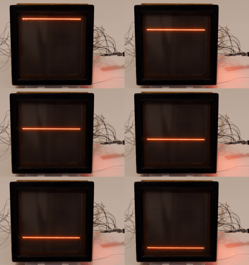
I replaced most of the logic board with an Arduino Nano. The only original parts used on the original board is the 12V→240V DC-DC converter, and traces feeding the 5V power through the board.
After connecting I checked that shifting values into the anode registers works correctly and that the cathode selection logic works by writing a number from 0 to 79 to achieve a full scan. Figuring out the order took a bit of looking at the logic board schematic.

There are two cathode counters combined into one 7 bit value. First counter on H3 (MSB), H2, H1 (LSB) counting from 0 to 4 and selecting which of the vertical lines in the 5x7 character is active. Second counter on H7 (MSB), H6, H5, H4 (LSB) counting from 0 to 15 through the full set of binary values, selecting which of the 16 characters in the line is active. Putting them together in swapped order (X3, X2, X1, X7, X6, X5, X4) gives us a 7bit binary counter which counts from 0 to 79.
If X3,X2,X1 is >4 then the decoder D6 in the bottom left of the anode logic board schematic selects a not connected output. This means there's no emitter pulled down on the cathode driver matrix and so none of the transistors pull down a cathode to GND.
You can download the Arduino code from https://github.com/Makdaam/MS6205-logic/tree/cathode_scan. It can be run directly as a Platform.io project, or the contents of main.c can be copied into the Arduino IDE. At this stage the code is so simple that I didn't divide it into multiple files.
 Leszek Jakubowski
Discussions
Become a Hackaday.io Member
Create an account to leave a comment. Already have an account? Log In.