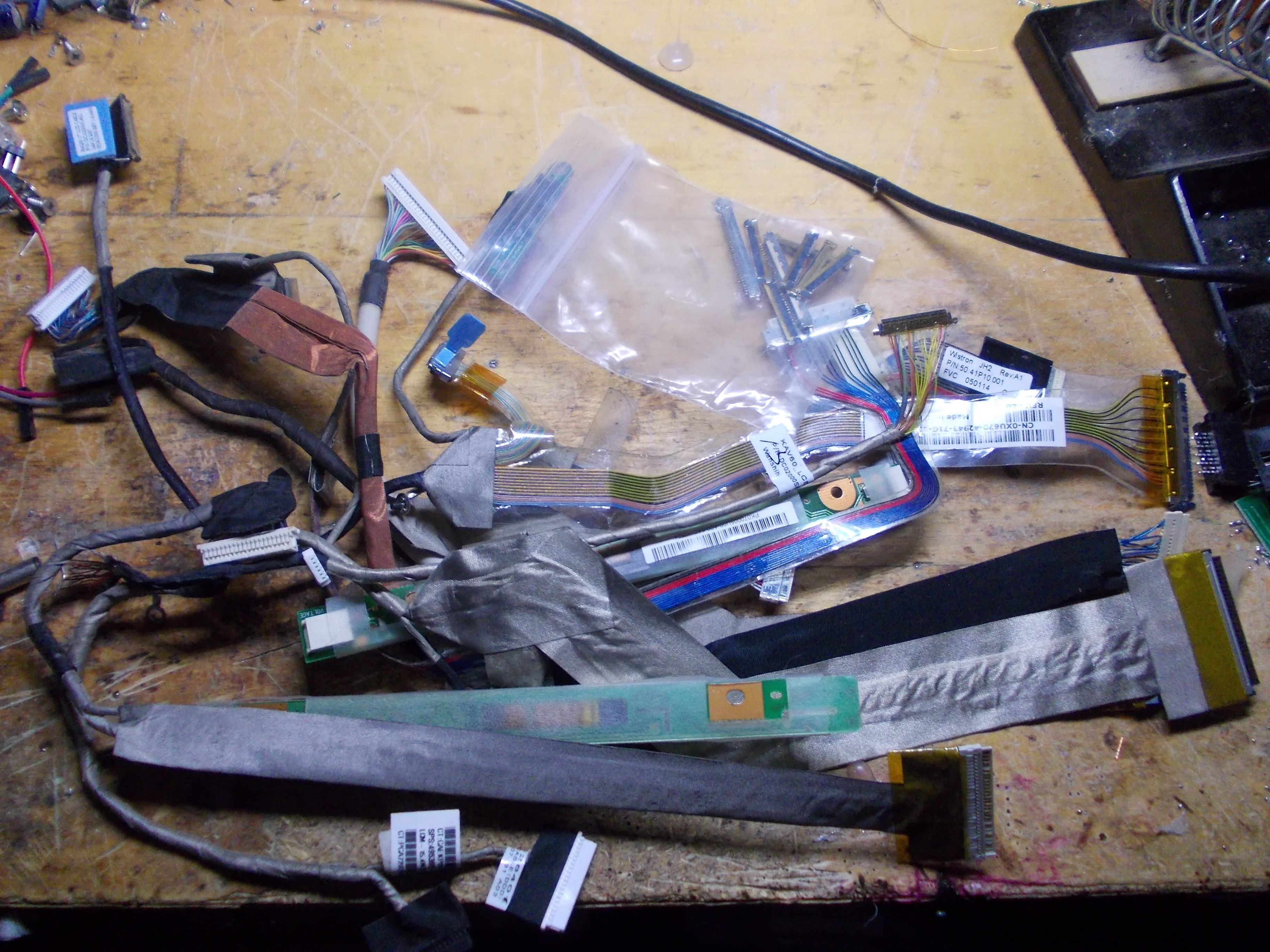
Laptop displays in their natural habitat use different cables than the controller boards do. These cables are, of course, not designed to work with a MT6820 or a similar board, the cable usually has a proprietary connector of some kind on its end that needs to be snipped off and replaced with a 2mm pin socket that a MT6820 board could accept, or connected to a small adapter board and an appropriate receptacle. That sounds like quite a bit of work, but actually, these cables are quite nice and often worth reusing.
- These cables work with the original display assembly - they fit nicely through the holes in the hinges, so if you're rebuilding a laptop with a new motherboard (i.e. building a Pi-based laptop inside another laptop's shell), reusing the original cable is a decent idea if the controller-suitable cable is too bulky.
- These cables are often well-shielded and won't radiate or receive as much noise, which is good if you plan to use them near sensitive circuitry of some kind.
- In case of CCFL screens, these cables also carry the inverter connections and plug into the original inverter used, which means you don't need to solder wires to the inverter and can use the original connector.
- Sometimes, they carry USB signals on a separate pair of wires, that USB is typically used for a webcam or a touchscreen, and you can reuse these wires as you see fit
- These cables are flat, which is a bonus for sleek designs.
The main problem, of course, is figuring out which wires on the proprietary end of the cable correspond to which connections. How do you do that?
There's two ways to figure out how to adapt a laptop's cable:
- Sit down for a couple dozen minutes and use the multimeter to map out the cable connections
- Find a schematic for the laptop the cable was used for and use that to see what connects where and why
Neither of these options are bad, the first option is guaranteed to work as long as you don't confuse anything, however, the second option is quicker and more foolproof. It requires two things - that you know which laptop the cable is from, and that the schematic is available. If you don't have both of those, you will have to fall back to the multimeter method.
Let's look at one of the cables I'd like to reuse:
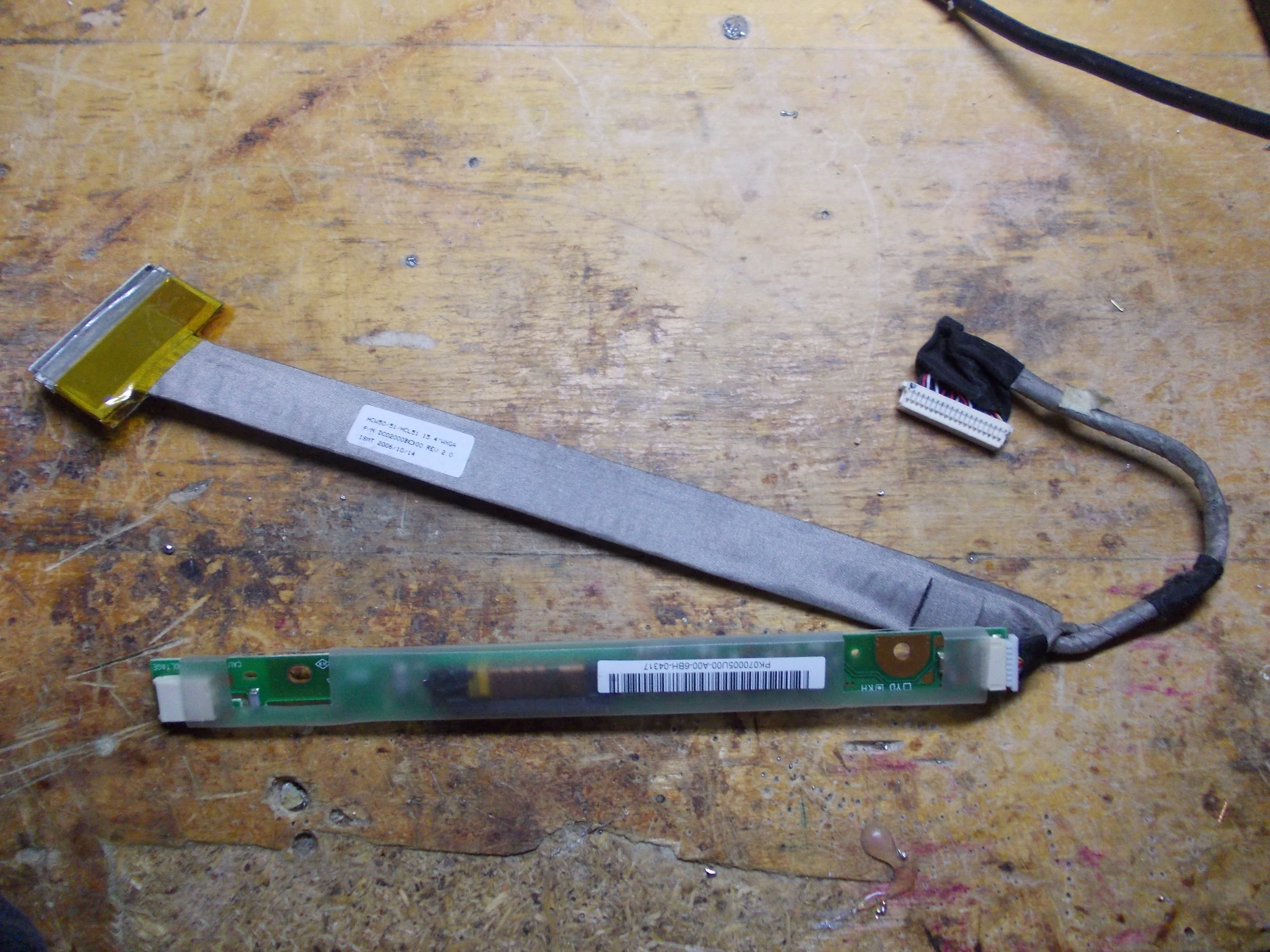
It's long enough (longer than the cable I got bundled together with a MT561 board), it has inverter connections, which is nice because I don't need to pull a separate cable, and it's also flat, which means I'll be able to make quite a sleek setup!
However, I don't know anything about this connector:
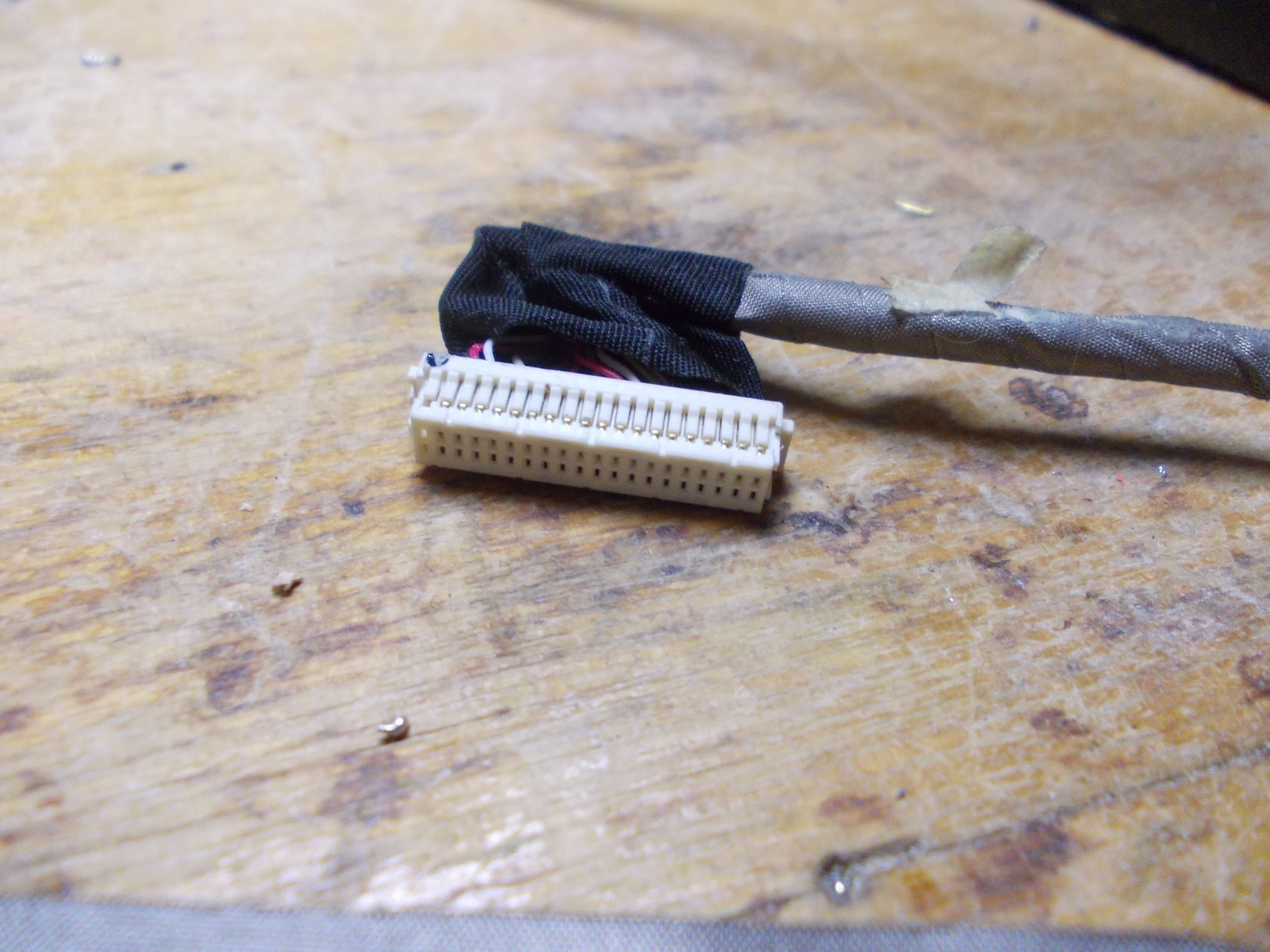
It's a connector I can get a receptacle for, these are some kind of JST connectors, but I'd need to design and order a board, that'd take a lot of time and not worth it for an one-off build. So, I will just get the wires out of this shell and solder them to a 2mm connector.
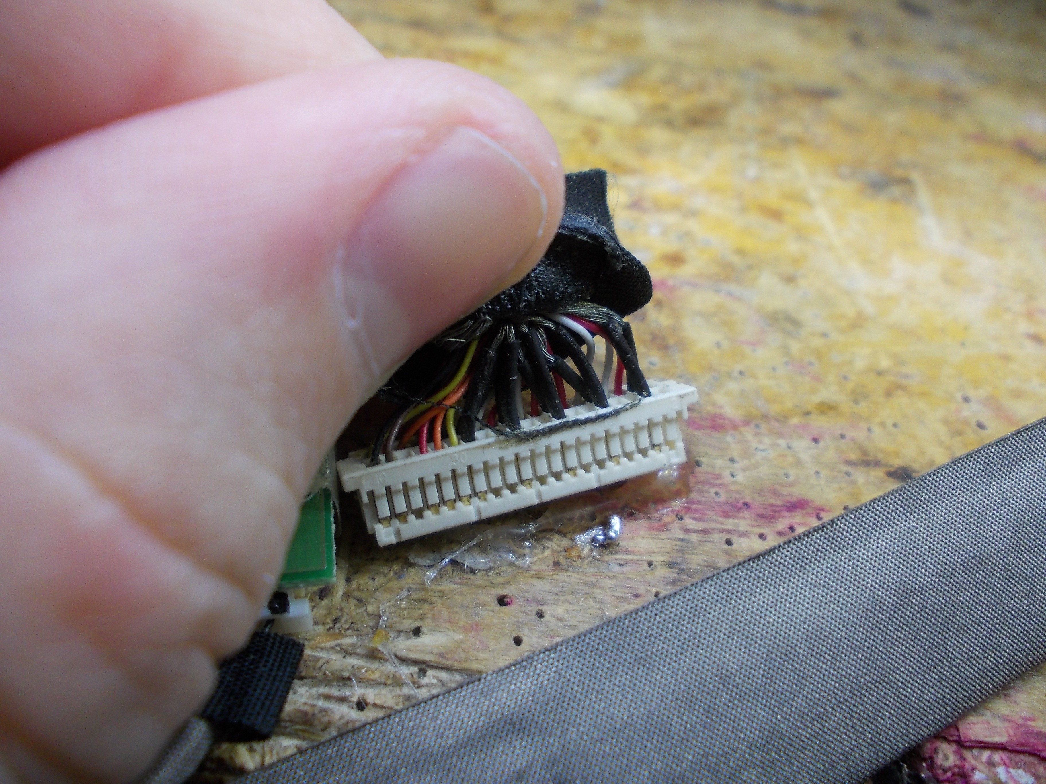
If I unpeel a bit of the tape, I can see that there's groups of wires that look like LVDS pairs - if I were to RE this connector without a schematic, it'd be a good start! The shield wires are, certainly, GND, there's more than enough of them, too.
[TODO: elaborate more about this cable's LVDS pinout and configuration]
There's one more thing - a marking on the cable:
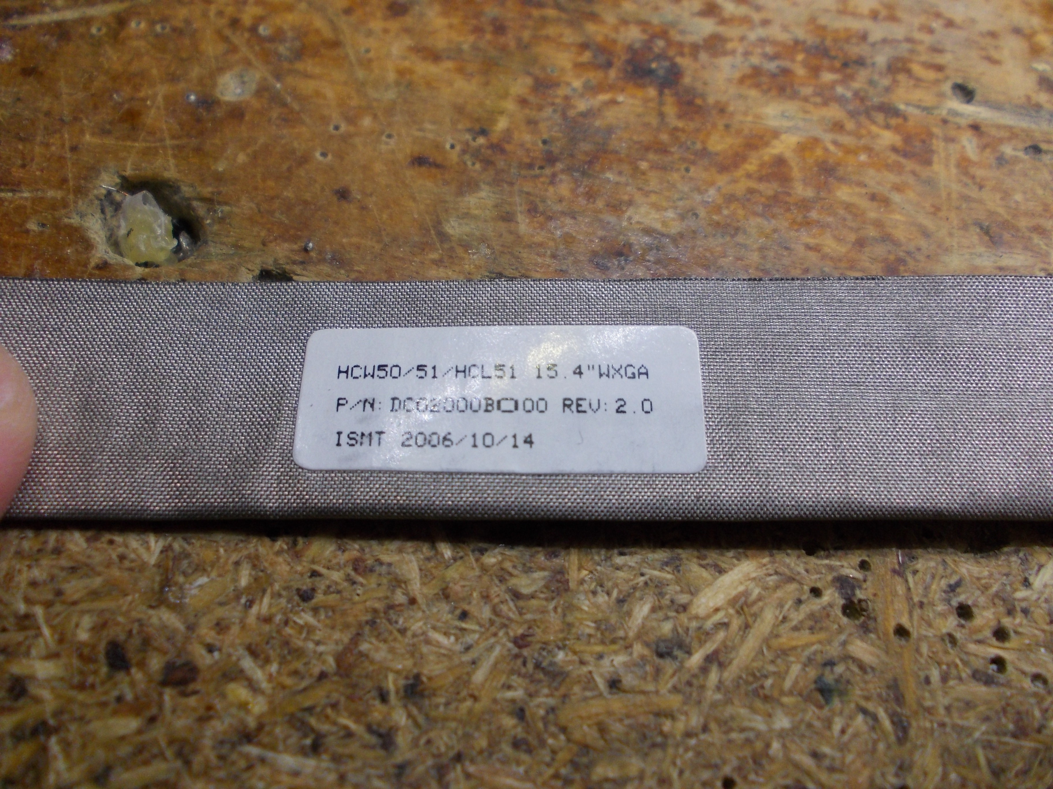
If we punch that into eBay, we get this:
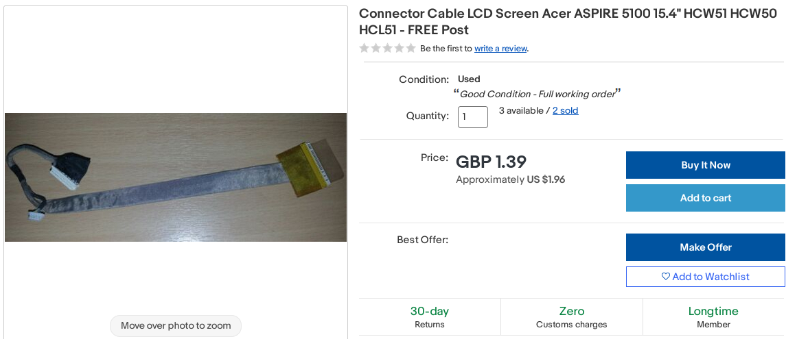
So, it's a cable for an Acer Aspire 5100. Do we have a schematic?

Yep, seems like we're in luck - schematics for these are available for free! One shady Google Drive link later, and we can skim through the schematic pages and find a pinout for the LCD connector:
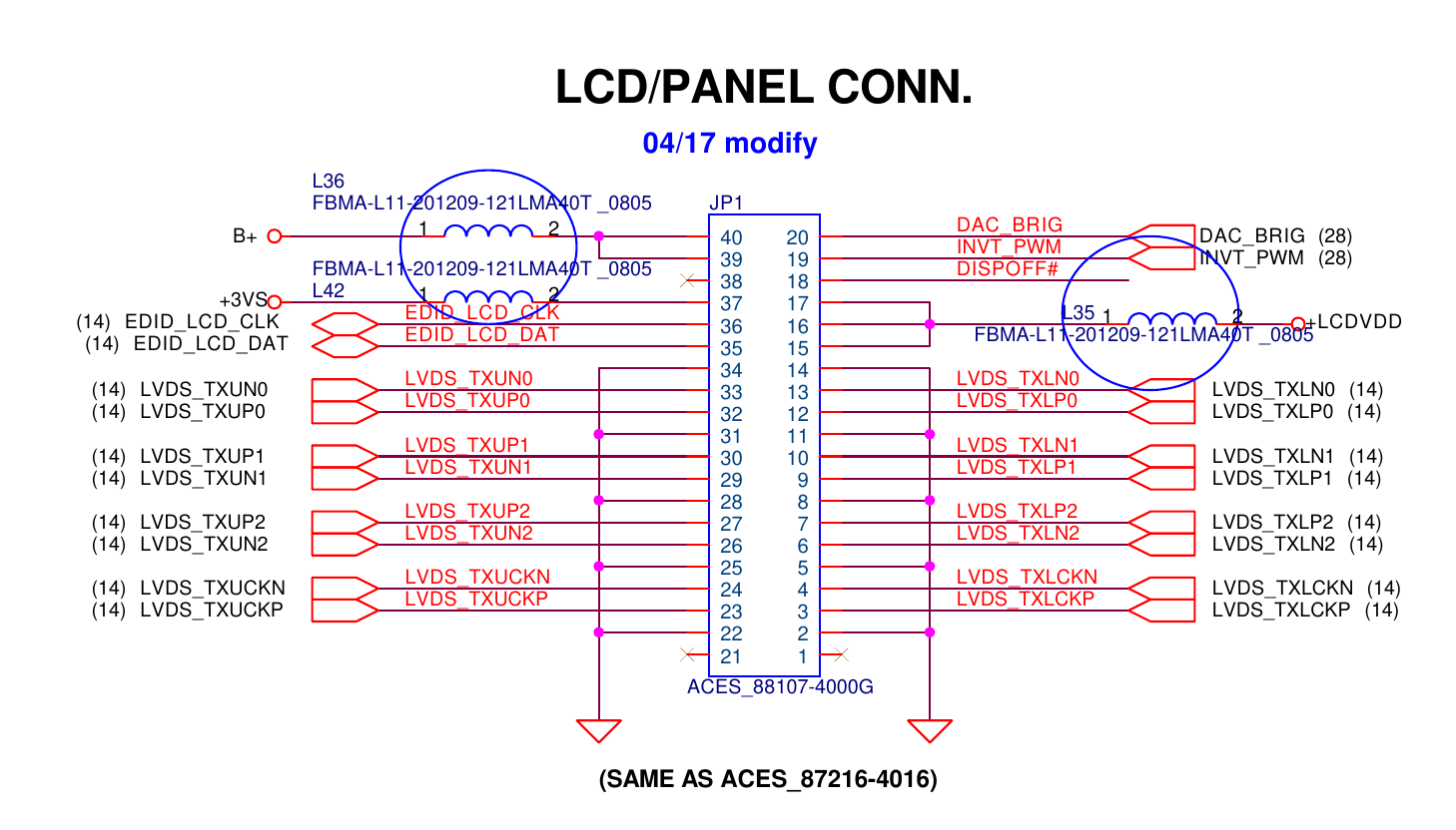
The B+ connection seems to come from the laptop's battery, and a multimeter check shows that it goes to the inverter board through a JST-SH 7-pin cable branch. LCDVDD wires go to the laptop panel's VCC pins, and +3VS goes to the VCC_EDID pin. DAC_BRIG, INVT_PWM and DISPOFF pins all go to the inverter board.
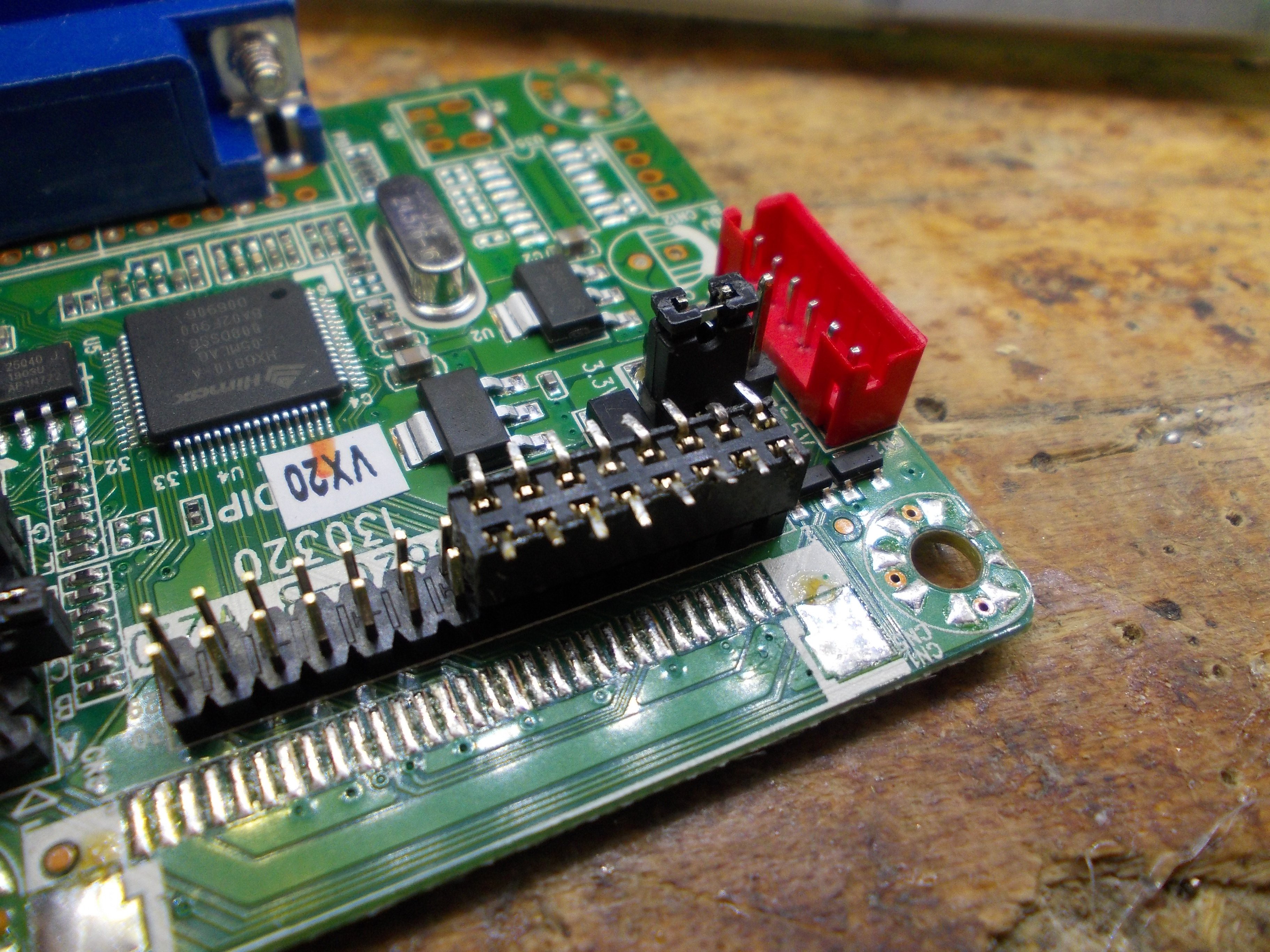
This is most of what we need for rewiring! This is a single-lane cable for a 6-bit panel, so, a 2x8 2mm pin socket will work wonders. An SMD pin socket will have pins we can solder to, so I'm using a 2mm 2x8 SMD pin socket on the MT561 board side.
[TODO: talk about microcoax cables and how they're significantly harder to solder to]
I decided to avoid stripping the wires I pull out of the original connector and instead plug them onto the pins, then solder them on:
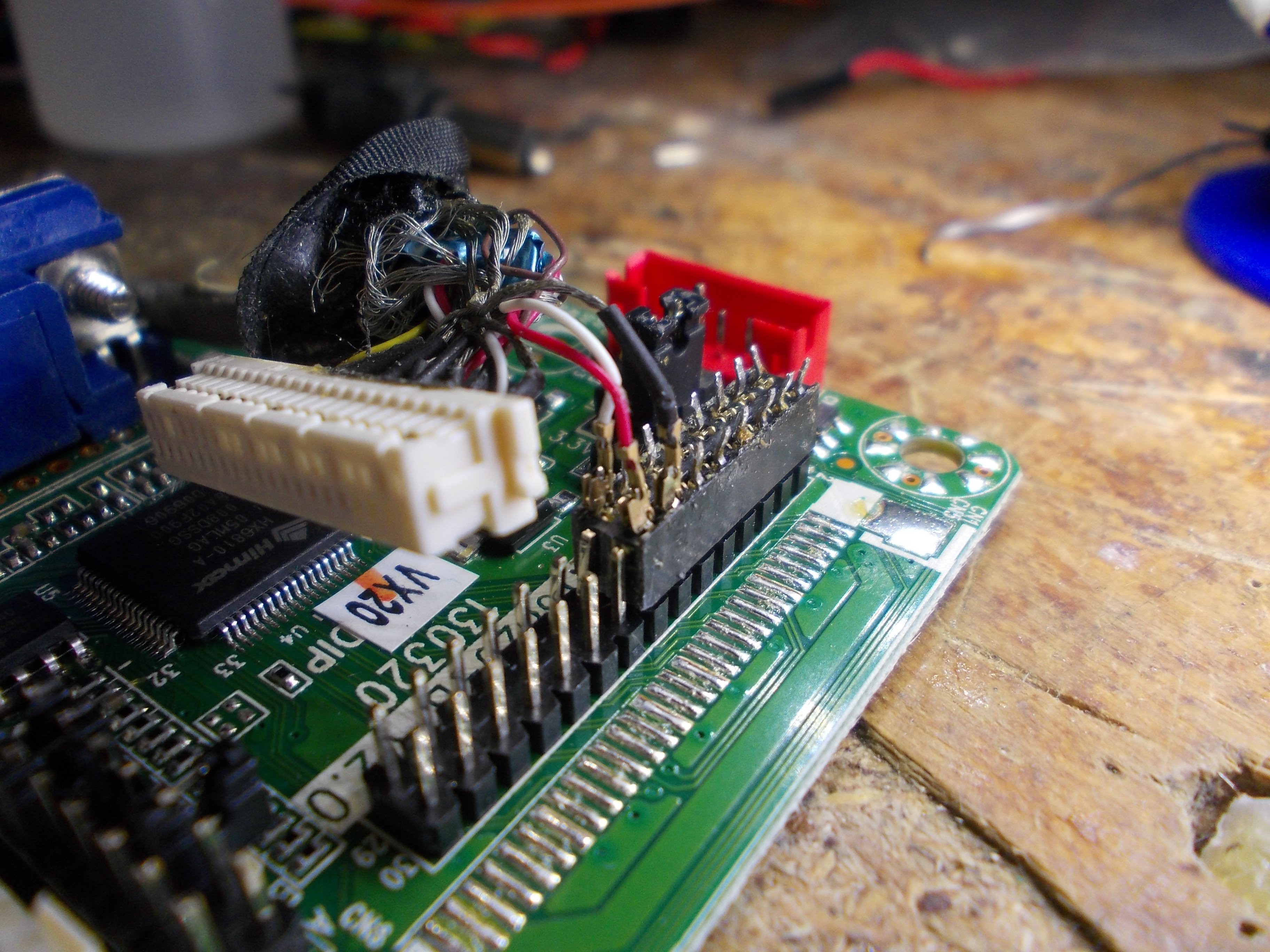
Soldering: [TODO: find a non-blurry pic?]
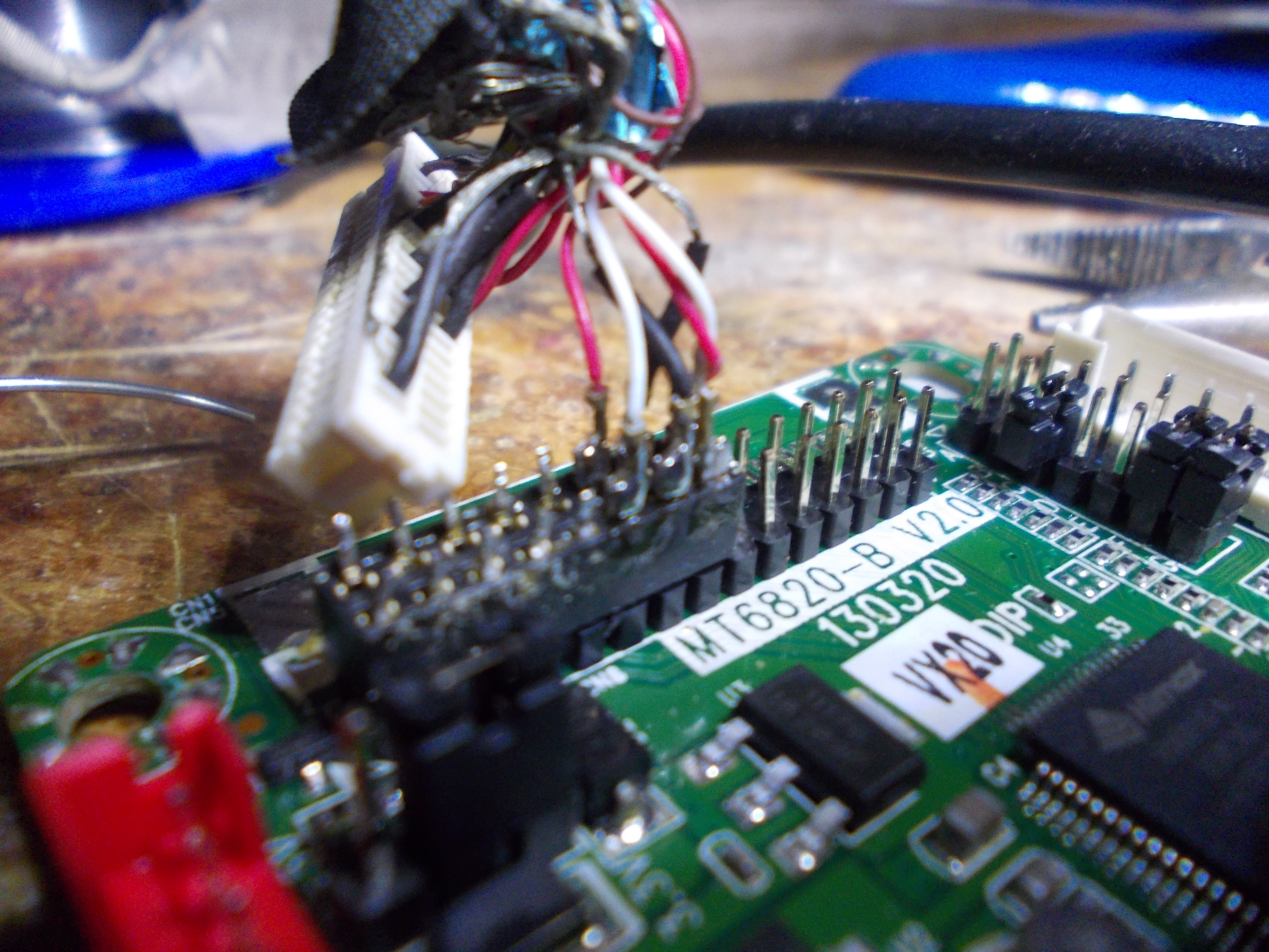
I also added a JST-5 connector to add an inverter connectoion that'd also plug into my MT561 board nicely. Sadly, I couldn't find a JST-6 cable in my collection, so I decided to plug it in a way where I only lose a GND pin - which I already collect plenty of.
[TODO: show the JST-5 connection and the finished LVDS wiring]
[TODO: elaborate on the inverter connections]
"How to draw an owl"-style, here's a finished setup:
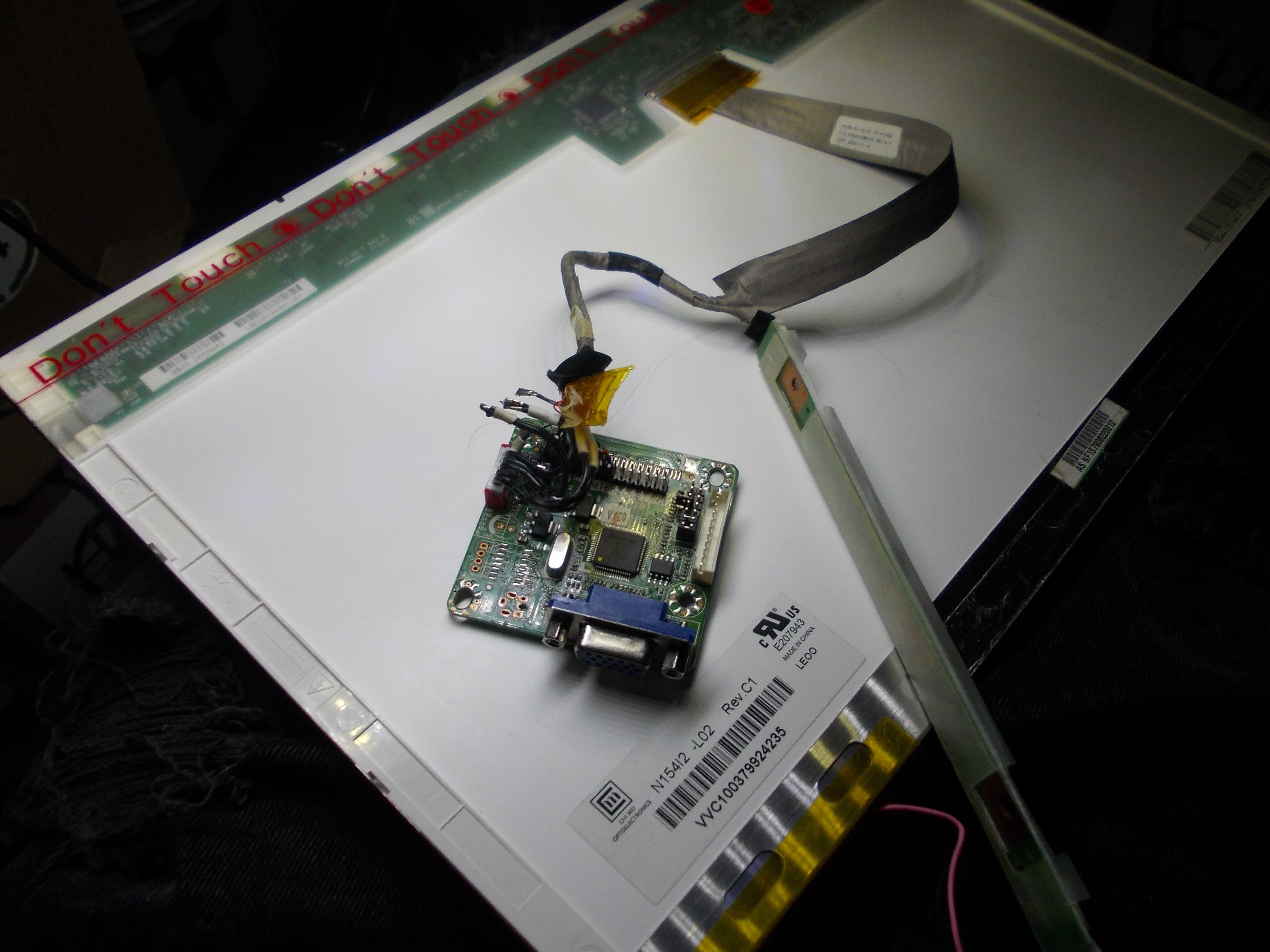
Needs to have power wires attached - ground, +5V for the controller and +12V for the inverter:
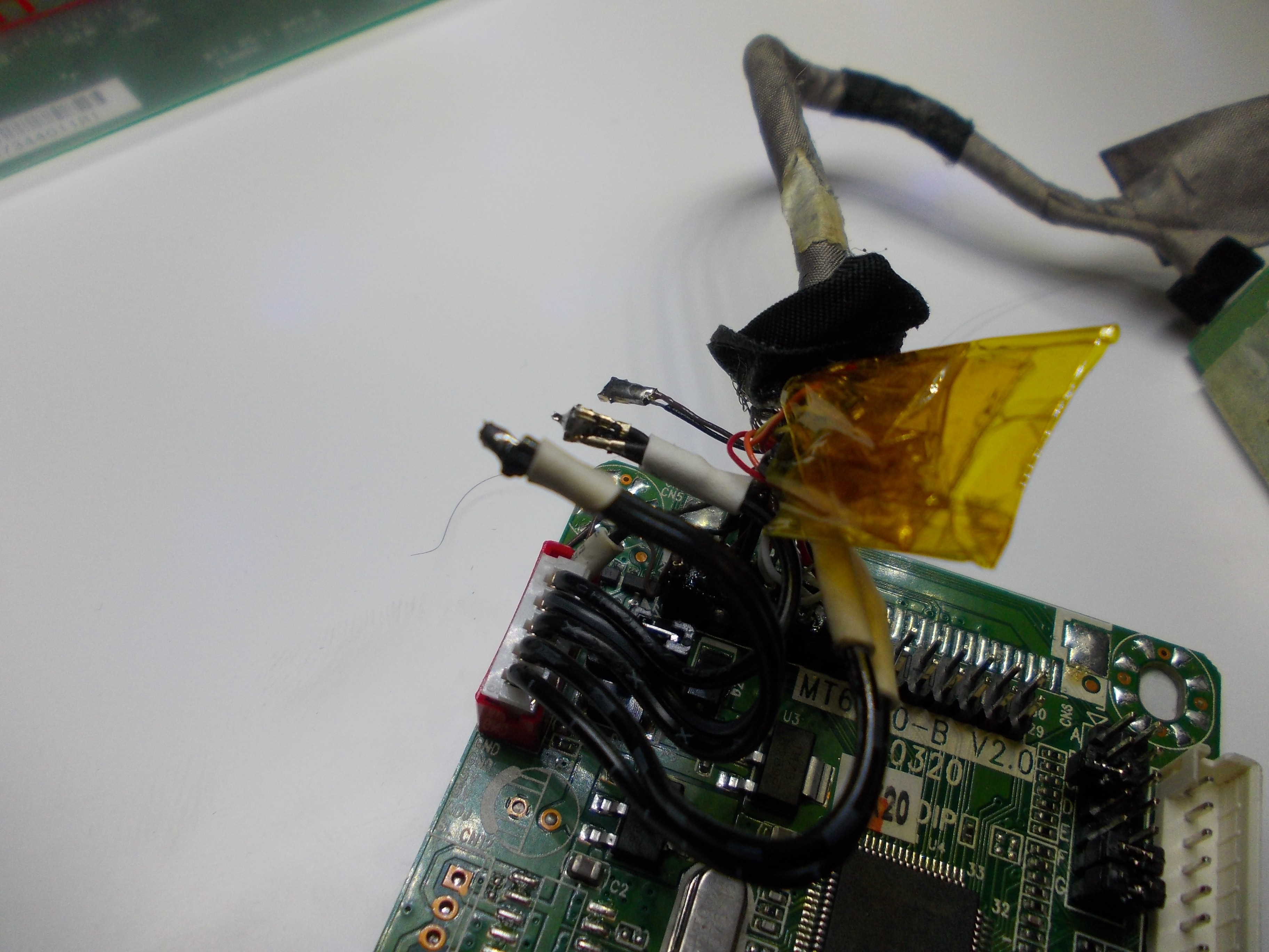
I don't have a picture of it, but I've added 5V and 12V to it by soldering an ATX PSU female plug to these three pins. In its current state, the MT561 board shows an image on the screen, but the inverter doesn't work - once I find time to make it work, I'll finish this post.
[TODO: describe bringup and solving the inverter troubles I have]
 Arya
Arya
Discussions
Become a Hackaday.io Member
Create an account to leave a comment. Already have an account? Log In.
I have the same inverter (from an Aspire 5610) working using the pinout a guy found in this thread: https://forums.tomsguide.com/threads/laptop-backlight-inverter-pinout.357343/
Are you sure? yes | no
Biggest pro-tip regarding laptop cable reuse... after multiple dead panels... don't be me (or a doofus in general, lol!). Also, that looks like a *very* standard 30 or 40pin LVDS connector.
Are you sure? yes | no