 Nuri Erginer
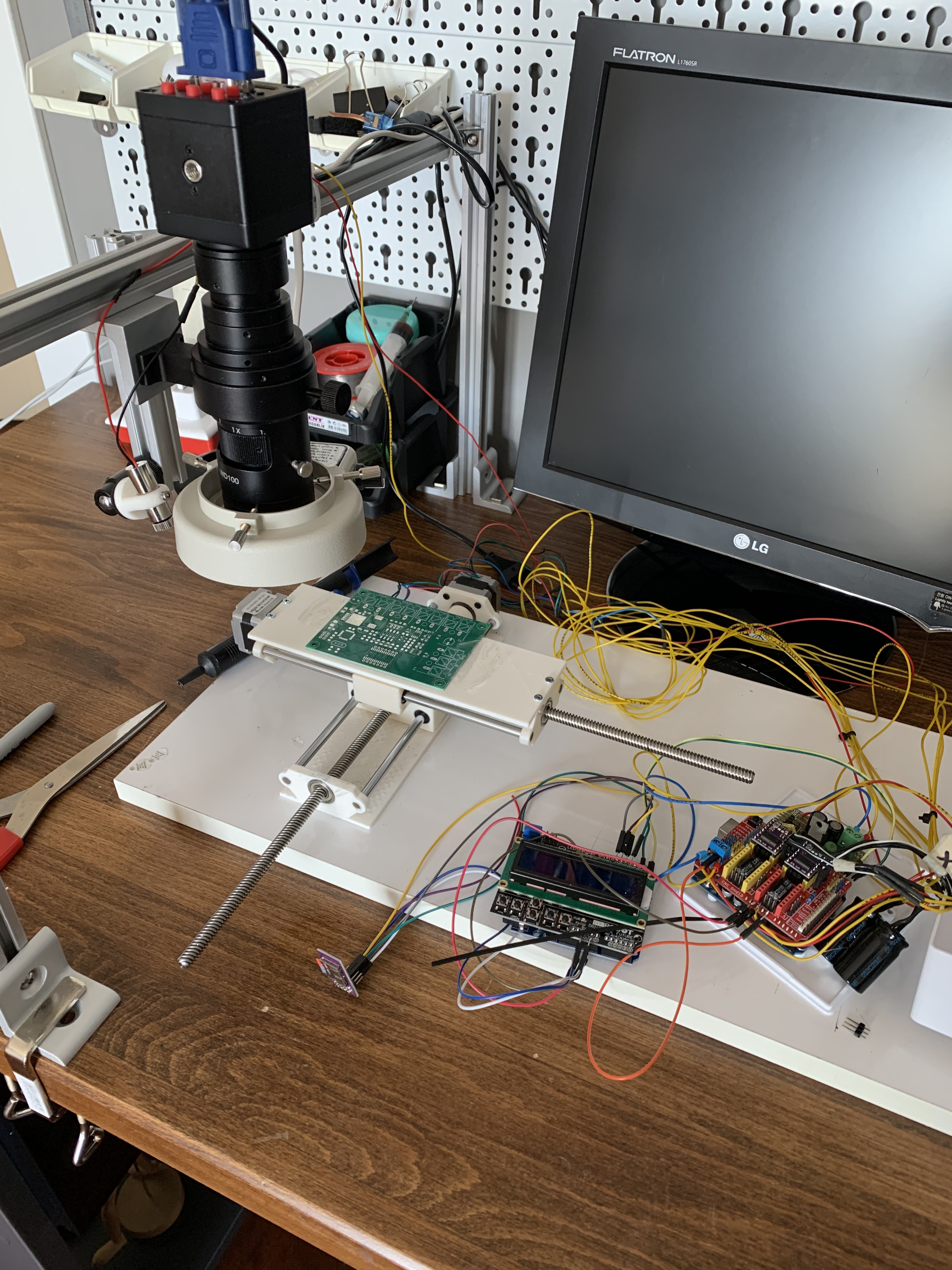
I started with a simple motorized cross table under the microscope for the proof of concept. I also use a cross laser beam to highlight the place of the component. It worked well. The down side of this design is I can not rotate the board while placing the component. SMT components has various orientation mostly 90 45 degrees on the board. So freely rotating the board gives me a lot of freedom while putting the component on the PCB.
Discussions
Become a Hackaday.io Member
Create an account to leave a comment. Already have an account? Log In.