 seasleyece
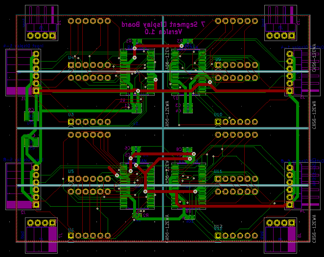
I started off with the display board design. The schematic and PWB layouts were done using KiCad as it is free an fairly powerful. The board design is fairly straight forward. Right angle .1" headers are used between the boards in the X and Y directions. The design contains four MAX7219's each driving eight 7-segment digits. A smattering of capacitors were tossed in for good measure as the matrix drivers can be real current hogs. The LED displays are 0.53" high.
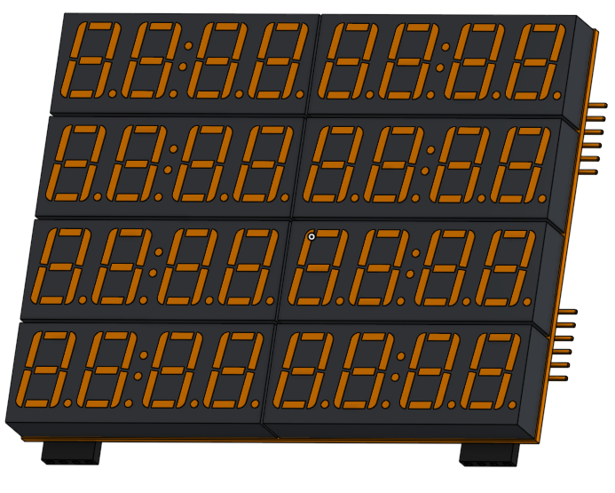
Once I got the layout done and thanks to the wonderful KiCad team I can view the design in 3D. Which is actually pretty nifty. The actual displays to be used do not have the colon in the middle but that was the only model I could find for the display size being used.
Discussions
Become a Hackaday.io Member
Create an account to leave a comment. Already have an account? Log In.