 Anton Poluektov
A few (or, in fact, quite a lot) modifications I plan for the next revision of the hardware based on my experience with rev. 2 so far.
Schematics:
- External pull-ups. The internal pull-ups in STM32 are around 40 kOhm, which means around 80 uA current draw per single key press (and up to 8*80=0.6 mA if multiple keys are pressed together). This is kind of excessive for the device that draws only ~15 uA most of the time on standby and 1-2 uA when off. For instance, if a few keys get stuck pressed while you carry it in your bag, it will drain the battery in days/weeks. External pull-ups of ~1 MOhm should solve this.
- Power circuit. Currently, power delivery is handled by a pair of Schottky diodes to switch between the battery and external power from ST-LINK when the programming interface is connected. However, even Schottky still drops the battery voltage by 0.2-0.3V. I'll make a simple mechanical switch instead (keeping the Schottky for ST-LINK just in case), which will also allow for a complete power off all the circuitry in case of any interventions like disconnecting the LCD (now I need to take the battery out for that).
- Test pads for debugging to simplify connecting oscilloscope or multimeter to some critical contacts like LCD signals or power rails.
- USART connector just in case?
- I was also considering more modern options for MCU (such as ARM32U5 which seems more power efficient) and 5V booster. Possibly, external switching power (SMPS) for STM32 would also make it more power-efficient, but that needs more investigation - not sure it's the case for the device that lives mostly in the switched-off state.
Casing and keyboard:
- I still want to play with different keyboard designs. The concept with keys made of PCB should work in general, but the keys that are completely floating in the air as they are now are rather wobbly. I plan to experiment with 3D-printed flat springs like I had in the previous design that attach to the keys.
- I know how to make the enclosure even thinner, down to 6.4 mm thickness! More on that when my next batch of PCB arrives from the service. The case will be made completely of a few layers of PCBs, with back lid and front panel based on aluminium core. The back lid will at the same time serve as the PCB for the keyboard switches and the battery holder, and the MCU-LCD part will be connected by a flex cable. Let's see how well it will work.
- The LCD will be upright (in the present design it's placed upside down, which causes some troubles in the firmware related to the text output).
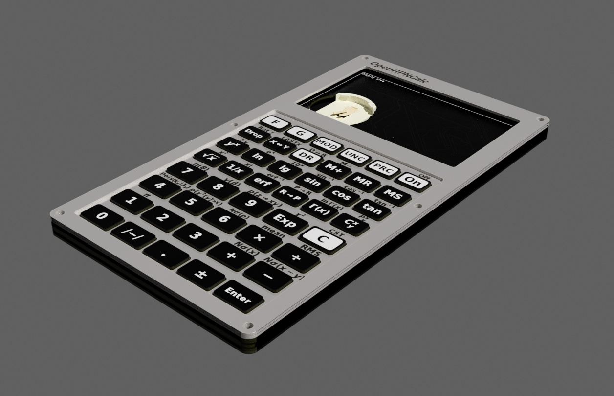
For now, I only have the render of the sandwich of all the PCBs from KiCAD imported to Blender (no LCD 3D model here). With such a tight design, checking everything in the 3D CAD program was essential, hope I haven't missed anything important. More news in a few weeks when the PCBs arrive.
Discussions
Become a Hackaday.io Member
Create an account to leave a comment. Already have an account? Log In.
Have you considered adding IR capability? It used to be used for printing only (e.g. in the HP42), and then later for device-to-device exchange (e.g. HP48).
If you were to consider such, I would humbly suggest using an IrDA module attached to some UART-capable pins as this will give you the most flexibility in your firmware for various features without having to later alter your hardware design.
Are you sure? yes | no
No, I was considering USART mostly as a debug interface for firmware development (e.g. with CircuitPython). Of course, one could add IrDA, Bluetooth etc., but I already have a cell phone with me ;)
Are you sure? yes | no