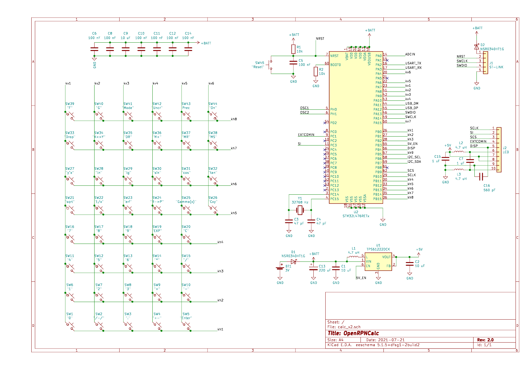
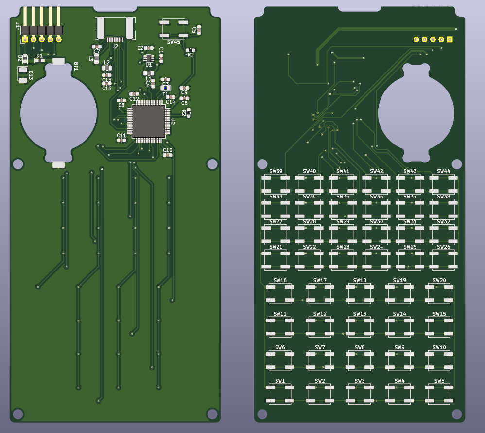
Based on my experience with the first version, I've made an update of the schematics and the v2 of the PCB is now ordered. Here is the list of changes:
- Additional filtering capacitors for STM (one per each pair of VSS/VDD(A) inputs as per datasheet) and for the LCD (according to LS027B7DH01 datasheet).
- Tantalum capacitor (220 uF) in parallel to the battery to avoid voltage drops during heavy processor activity when the battery is weak.
- Power pin on ST-Link header to power the calculator while flashing or to measure current consumption. Two Schottky diodes as a protection when both ST-Link and battery power is on, and to protect from reverse battery polarity.
- New battery holder (Keystone 1057) which sits in the cutout of the PCB to reduce thickness of the enclosure.
- Improved PCB layout for TPS61222 voltage booster (following datasheet)
- More compact PCB (126x64 mm) with screw holes and cutout for LCD flat cable.
New schematics

New PCB:

 Anton Poluektov
Discussions
Become a Hackaday.io Member
Create an account to leave a comment. Already have an account? Log In.
Wow, this is really cool! Have you already received the new PCB? Does it solve known problems? I'm very intrigued with how this idea with a battery holder works.
Are you sure? yes | no