Retro Alphanumeric LED Displays + Libraries
Exactly as the title says, these are a few retro led displays I've strung together to make 16x2 modules with some software I wrote
Exactly as the title says, these are a few retro led displays I've strung together to make 16x2 modules with some software I wrote
To make the experience fit your profile, pick a username and tell us what interests you.
We found and based on your interests.
pdsp_example.inoPDSP Arduino IDE Example Software (for Atmega328P)ino - 5.90 kB - 05/24/2021 at 13:42 |
|
|
pdsp_matrix_2021-04-21.zipPDSP PCB GerbersZip Archive - 365.27 kB - 05/24/2021 at 13:36 |
|
|
pdsp_matrix.schPDSP Eagle Schematicsch - 800.18 kB - 05/24/2021 at 13:36 |
|
|
pdsp_matrix.brdPDSP Eagle PCBbrd - 158.20 kB - 05/24/2021 at 13:36 |
|
|
DL1414.schDL1414 Eagle Schematicsch - 427.97 kB - 05/24/2021 at 13:35 |
|
I made a quick video demoing how a clock/weather monitor application would look. I show off both the yellow and green displays I have as well as an idea I had about using some mirror window cling film with some plexiglass to increase display visibility. In the end I think I'll just order manufactured mirror plexi as I suck at applying the film by hand (way too many visible imperfections).
My plan is to make a wifi clock with the pdsp display I've designed, and have it also show the weather which it'll grab with the use of the openweather api. I wanted to explain a bit how my library handles text to be displayed. There's two types if text my library can display, static text that once written is permanently displayed until erased/overwritten and scrolling text (which obviously scrolls). The static text uses the function writeString which takes arguments x, y and str. X and Y are the coordinates where the first character in the string str will be written. In my 16x4 display example, x=0 y=0 would start the text at the very first character in the upper left corner of the display (indices start at zero, where 0<=x<=15 and 0<=y<=3). If the string is longer than 16 characters, the width of the display, the string will wrap around to the next line until the entire display is filled but will cut off the string after the last character in the lower right character.
For scrolling text, I've written the function scroll which takes the arguments line, pos and str. My implementation is pretty simple and could definitely be simplified more to require less user intervention but it's simple and it works so I'll leave it alone for now. Line tells the function which line you want to scroll, pos is the current scoll position, and str once again is the string to scroll. So for example:
String test="Now: Sunny 74, 3PM: Cloudy 68 ";

int t=0;

while(1){

    scroll(3,t,test);
    if(t<(test.length())){t++;}else{t=0;}

    delay(1000);

}
Here the string test will be displayed on the last row and will scroll at the rate defined in the delay (in milliseconds, decreasing number will speed up scrolling). It's necessary to check the position each iteration so that the nothing beyond the end of the string will be displayed (which would likely just spit out unintended junk characters out of bounds of the string). Scroll direction or even starting position could easily be changed by tweaking the t++ to decrement instead and the initialization value of t, respectively.
Finally I've implemented a control function to allow changing brightness/flashing functionality built into the led controller modules, a clear function to clear the entire display, and a UDC function (user defined character). Each led module can store up to 8 user defined 5x7 characters to allow custom icons or fonts. At any time the UDC function can change any of the eight udc characters. It take three arguments: addrUDC, chr, and c. This gets a little confusing but basically my 16x4 display is really made up of 8 led modules (where 0<=c<=7). So you have to tell the function which of those 8 modules you want to talk to. Then addrUDC will tell that module which of the 8 user defined characters you want to overwrite. Finally the character array chr contains the custom bitmap character you want displayed. After a UDC is defined and saved to one of the modules, then you can tell the module to display it, for example:
unsigned char custom[] = {0b01110,
                          0b10001,
                          0b10001,
                          0b11111,
                          0b10001,
                          0b10001,
                          0b10001};

UDC(0,custom,disp1);

disp_write(ChrRAM|7,UDC0,disp1);
The custom character array 'custom' represents the horizontal slices of the desired image (I wrote it out as binary so you can visually see the character, in this case it's the uppercase letter A).
The UDC function call takes that custom array and writes it to UDC0 of display 1.
The disp_write function then selects disp1 is module 1 where UDC0 and ChrRAM|7 tells it you want to display UDC0 at position 7. I'll admit it's a very convoluted way of doing things, but it works well enough once you understand it.
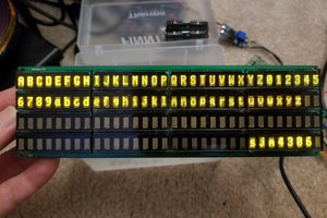
So that worked out pretty well for the DL1414 LED displays, so let's try even rarer LED displays that can do full 5x7 alphanumeric characters. I found a few lots of PDSP-1881 and 1884 8 character displays (a total of around 20 displays each) on ebay a few years ago without breaking the bank (I think I paid about $60 for the whole shebang). The problem is now they are even harder to find and thus much more expensive (last I checked about $30-40 per display!!!). So what should I do with these beauties? Well why not give them the same character matrix pcb treatment as the DL1414's?
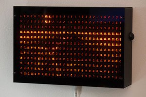
I went full out on my first iteration and made a massive 32x4 matrix.
Yeah but there was a few ... issues with this iteration. First off only the chip selects for all 20 displays were wired to shift registers, the rest of the required parallel io needed to be wired to gpio (this meant I needed a good 25 or so free pins on whatever chip I wanted to control the displays). In the pic above I ended up using a PIC16f887 to control the display but even then I used up nearly all the gpio on the chip so that was all it could interface with. The PIC is hidden under the display but I tell you it looks like that scene from the Matrix with all those cables wired to Neo when he wakes up in that energy harvesting pod/tank in the real world.
A second major issue was with all 128 characters lit the display as a whole consumed well over an amp of current (and got toasty enough to ... well erm toast toast ...). This coupled with the lack of decoupling capacitors (pun unintended) on the board (an embarrassing oversight sure), meant the display was prone to browning out and crashing the pic in the process. So as a proof of concept this iteration wasn't a complete failure ... but it kinda was a complete failure as a practical implementation.
So back to the drawing board, I decided to pare the display down to 16x2 to limit max power consumption and generated heat and also decided to decrease the gpio requirements down to a single spi serial port by using shift registers to drive all required pins of the display. This effectively meant I was trading hardware complexity for software complexity.
This is the design I settled on:
Notice the large bulk tantalum decoupling cap right at the power input pin and individual ceramic local caps at each display, looks like I really had my thinking CAP on when I was designing this board! Anyway, bad dad puns aside, I really wanted to mount the smd shift registers on the back and make the pcb barely larger than the PDSPs mounted on the front but it ended up being too tight a fit for a two layer board so I just went the easier albeit less aesthetic route.
I threw together two boards as soon as they arrived from JLCPCB (obviously one each for the 1881 and 1884, yellow and green display versions respectively). Here's a pic I shot as soon as I got the software working properly.
A beautiful display at full brightness with all characters lit without any thermal or brownout issues! So looks like the onboard caps did the trick.
For the software side, I ported my standard assortment of string/custom character/location write functions. The bit that took longer to get working was the function to actually generate the correct clock/data signals to write to each display. Initially I had all the bits backwards (that was a fun facepalm, but easily fixed). Then I found I was getting gibberish due to forgetting to wire up the read pin correctly so it was randomly floating, cause really weird write behavior (don't worry I bodged this first rev of pcbs and already fixed the eagle files/gerbers). In the end though both the pcb and software seem to work reliably enough so I guess I can finally call this a success for now. So what's the plan for this display ... well I was thinking of making a desk clock that would scroll weather, traffic and grab the time off of wifi. Seeing as this display looks very much like those much...
Read more »So here's my entry to the 2021 HAD Prize: Rethink Displays. The problem I want to address is twofold: high visibility in any lighting condition and display longevity. While I could address one or the other with either modern lcd or oled displays, doing both is a little more complicated. This is why I opted for using vintage alphanumeric led modules, while they certainly aren't power efficient it's hard to argue with their brightness and reliability (similar tech was often used in military/aircraft readout display applications). For this project I demonstrate prototypes for two such led displays composed of smaller modules all controllable through a simple serial interface and library. The first is much more primative than the other being limited to 14 segments and the latter is able to display full 7x5 alphanumeric characters (and even custom characters).
For all source/design files shared through this project, I'm not the lawyer type but my intention is to provide them basically with free reign for non-commercial purposes. This means feel free to recreate or modify them to suit your application so long as you don't intend to sell them as/in a product (if you do want to sell something based off of my work please contact me first to get terms/permission). And obviously any derivative of my work must inherit the same permissions I've just explained. Now with that out of the way ...
To start off, thanks to JLCPCB for sponsoring this project as well as providing pcbs to get the ball rolling. JLCPCB Prototype for $2 (Any Color): https://jlcpcb.com
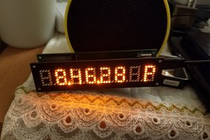
I'm certainly no stranger to vintage LED displays (... well vintage displays in general I guess), so when I found these adorable 4 digit 14 segment DL1414 LED bubble displays on aliexpress for roughly $0.70 a piece I had to buy a handful. I have no idea what I plan on using them for but I felt the urge to strap a good few of them together to build a larger display. I figured emulating the venerable commonly available 16x2 lcd would be a good starting point and would only require 8 of these chips.
Each display has 7 data inputs, 2 address inputs, and a write enable input pin. To write something on the display you need to set the ascii value for the character you want displayed (these are alphanumeric having 14 segments per digit after all), set the 2 bit address for which of the 4 digits you want written to, and finally strobe the write enable pin. The exact timing requirements and signalling order is described in the datasheet, but this gives a general sense in what is required from a microcontroller to write to a single chip. My issue though is I want to be able to write to 8 chips using as few pins as possible. The solution: SHIFT REGISTERS!!!
I opted to use three 74hc595's in series to give me 24 pins to toggle in whatever pattern I wish while only using 3 SPI control outputs from a micro (and an optional pulled down 4th output enable pin to disable all shift register outputs). The trick I used is many of the pins between the 8 chips can be tied together. For example the 7 data inputs can all be shared among the chips in a bus since only one chip will ever be updated at once. The same goes for the 2 address input pins. So far we have 9 pins driven by the total 24 pins on our shift registers. What differentiates the chips and allows my micro to write to specific chips is the write enable pins. Each chip's write enable gets its own signal from a different output from the shift registers. So now we are up to 9+8=17 out of 24 pins on our shift registers. This is where I stopped but we'd actually be able to add an additional 7 chips without having to add any more shift registers. I just ended up breaking out the remaining 7 pins to test pads. However, for me 16x2 was a nice round number that I was happy with.
So now that we can control 32 individual digits with a minimum of 3 SPI pins (4 if you want to dim them) lets throw together a nice pcb to mount them all and write some...
Read more »
Create an account to leave a comment. Already have an account? Log In.
I like this type of display too. In my case, I used 12 HCMS-2972 to make a serial terminal. Since the data is serial input, the interface was simple with a daisy chain, but I had a hard time with the software because I had to generate the font pattern from outside and input it. The brightness of the display is set to 30% in order to reduce power consumption.
I absolutely loved your serial terminal project! I have a few HCMS series displays as well, yes they are significantly easier to daisy chain on a single SPI bus but lack the internal font data like you've mentioned. I actually prefer that though as I usually like to implement multiple fonts in the microcontroller, but with the PDSP there's only a few user definable characters so I'd have to constantly be rewriting them to utilize a full font.
Thanks. These display devices can be a challenge, but it's fun when we get it just the way we want it.
Those are some sexy displays. Good work on making them live. Love their look.
Become a member to follow this project and never miss any updates

 sjm4306
 Chris Combs
 SAYANTAN PAL
i have lots of Simens PD2437, do you think they will work the same way? i would love to get a use for them! this is an awesome project!