 lion mclionhead
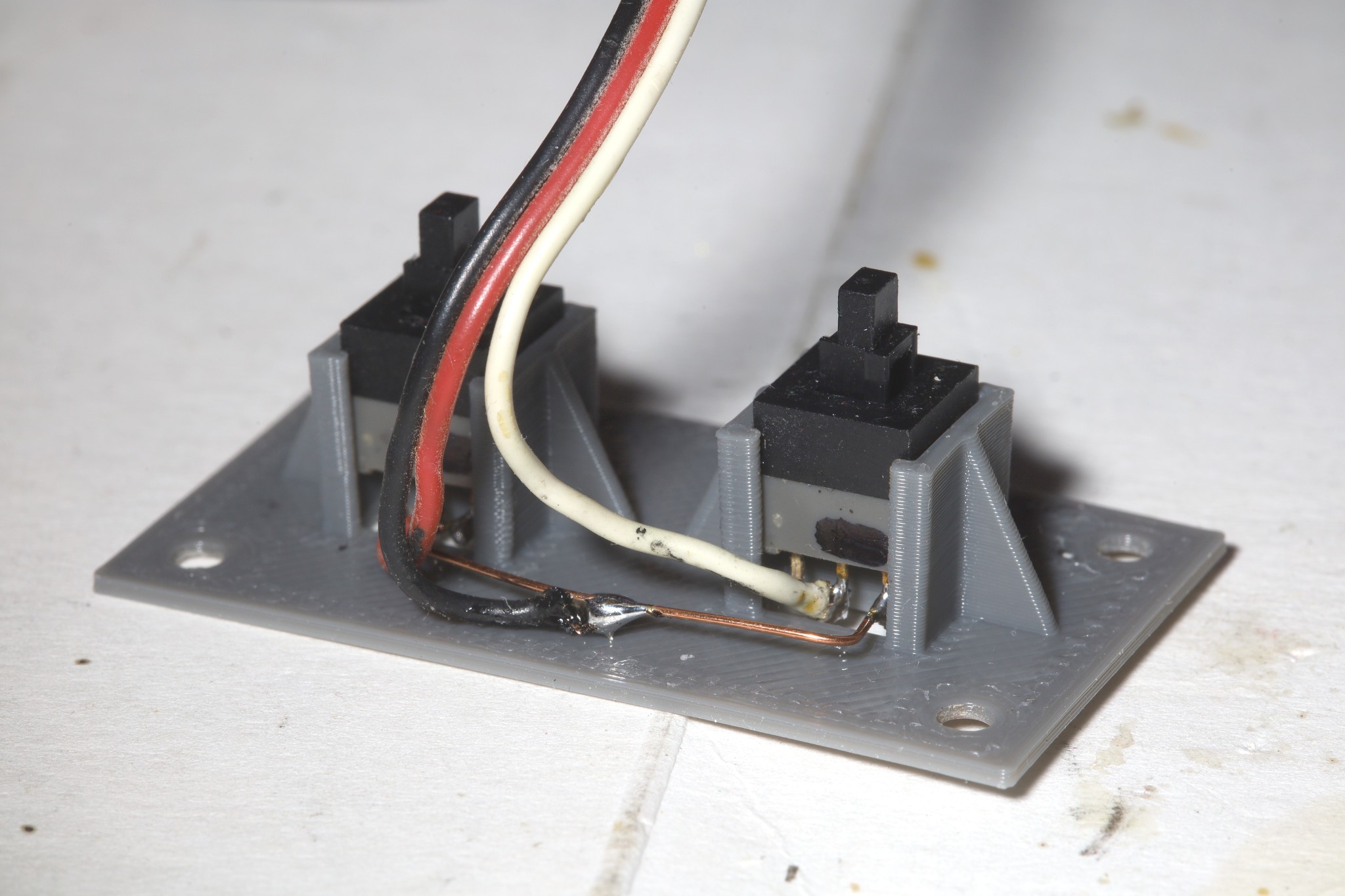
Years of declining results with the pinball buttons led to finally designing something with MHPS2283V's. This was the 1st design to try to use friction to mount the buttons.
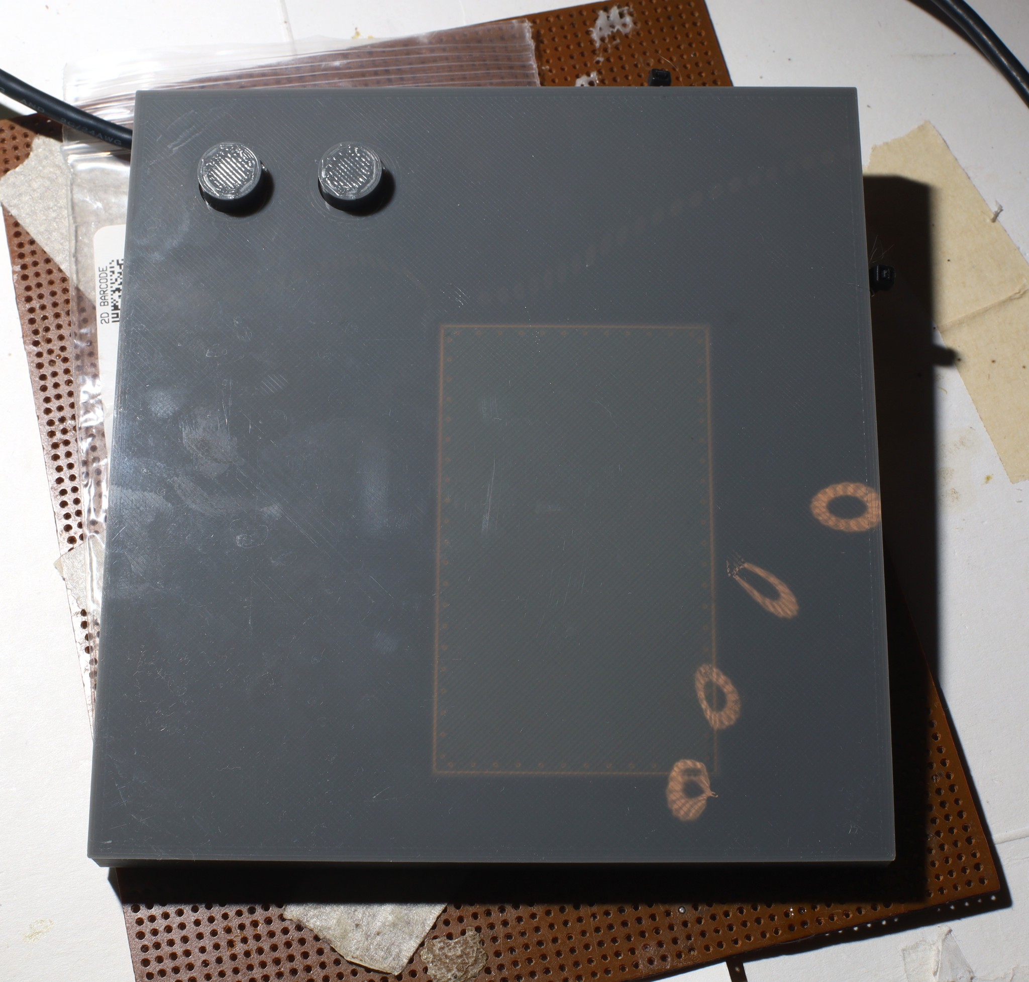
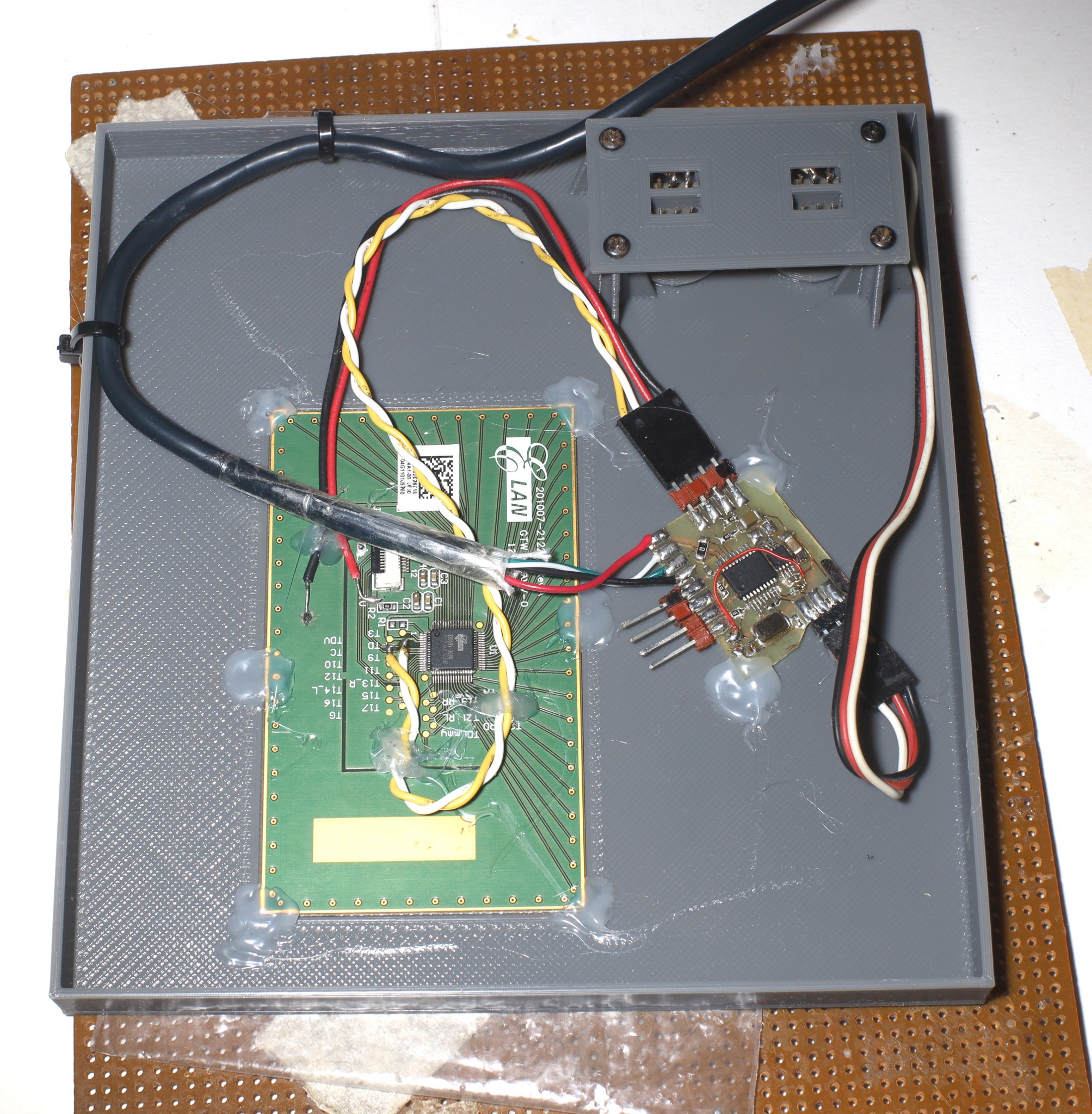
In the previous design, the touch pad was on top. This design had it under .4mm of PLA. With it on the bottom, there was less room to mount the circuit board.
The touch pad seems to work better with .4mm of PLA on top than it did with packing tape on top. It detects less false positives. There is an annoying slapping sound from the PLA slapping the touch pad. Laptops work around this with horrendous adhesive. When wearing headphones, it's not audible.
Packing tape might have been a quieter solution than PLA. Packing tape could be sandwiched between 2 panels but it would be a pain. The touch panel would be on a platform secured with farsteners instead of hot snotted. No touch pad was ever usable for free paw drawing though & therein is the real desire.
The USB cable is a pain. A guy managed to get viral with an NRF based wireless wheel.
He just used the SDK without knowing how the power management worked. It would entail another NRF eval board. An alternative is just using a custom radio with a USB board, but that would require detailed power management.
Discussions
Become a Hackaday.io Member
Create an account to leave a comment. Already have an account? Log In.