So I've been wanting to do this project for a long time, awhile ago myself and a couple friends were interested in long range XBee radios frm Maxstream. The prices were pretty high at the time so we thought about rolling our own PCB for one of the wireless chipset that Maxstream used. Though at the time we had no experience in PCB design let along designing RF PCBs. So after a few years of gaining experience designing all sorts of things, I decided to explore this project again.
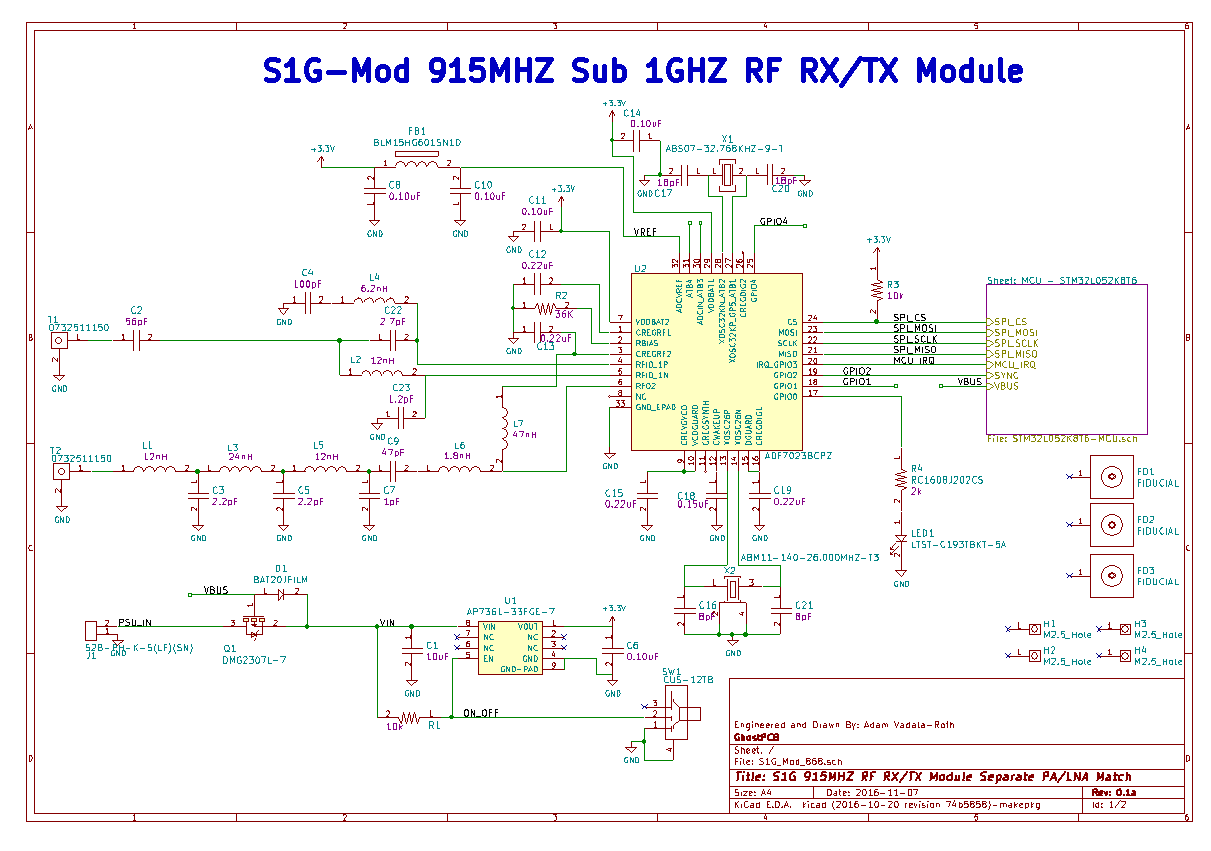
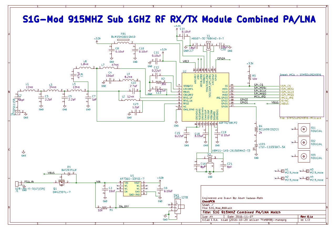
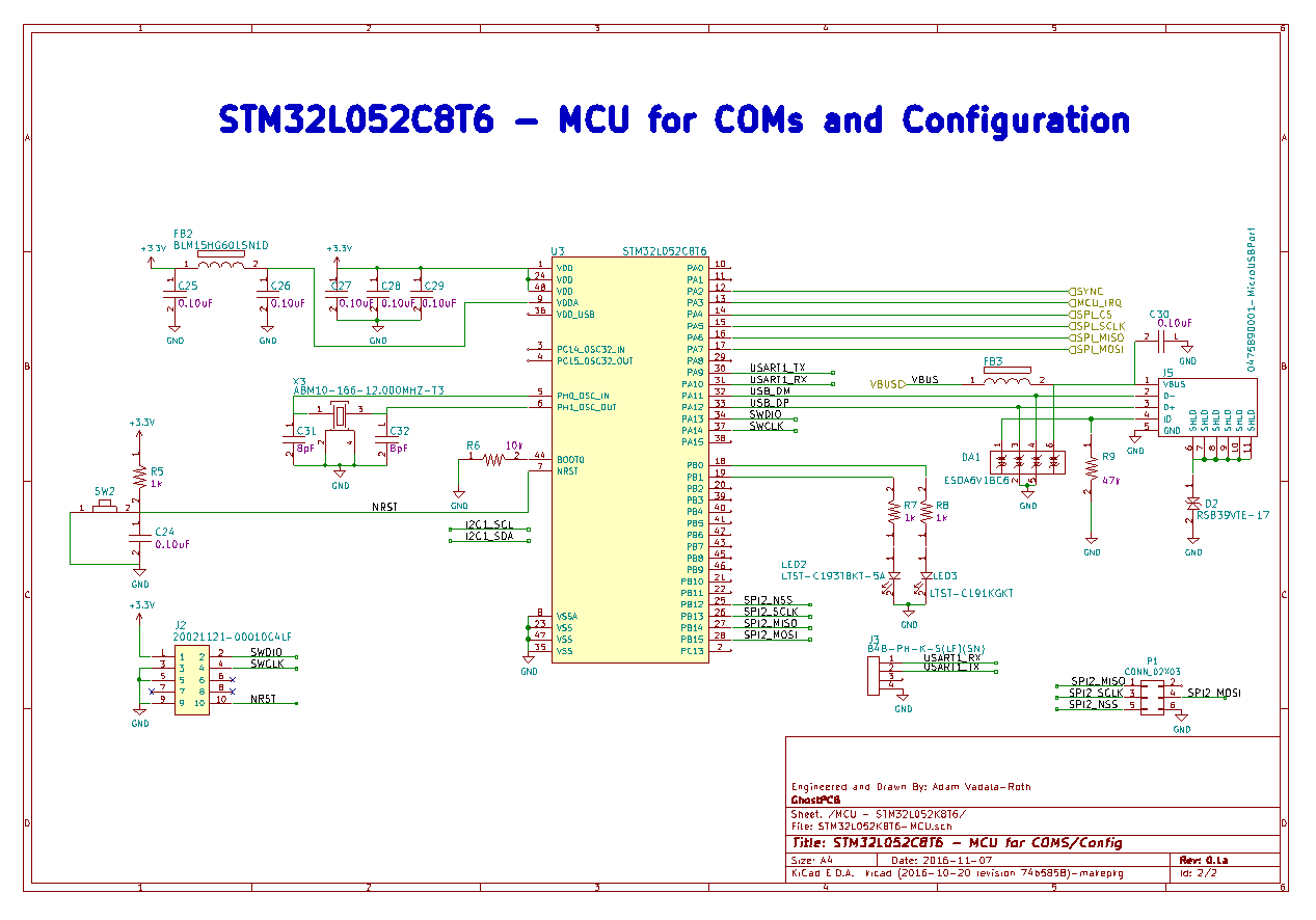
With that I did some searching of RF transceivers and came upon the ADF7023, its a pretty nice chipset and supposedly capable of transmitting at a fairly great distance. The modules I will be developing will essentially be ADF7023 + STM32 ARM Cortex M0+ on a board with SMA antennas, several connection ports, and USB. The RF section is nearly a straight implementation of the reference design but some components have been swapped out for ones with better tolerance and RF grade. The rest of the schematic is orginial to the project. At this point I've created two schematics, one for separate and combined PA/LNA matches. This should let me explore the capabilities of the chipset and allow me to build 4 unique radios, for 433MHZ the baords will be the same but components changed.
Here are the Schematics:
Separate Matches

Combined Match

MCU Section, its the same for both boards:

So that;s where I am at currently, these are subject to change a lot over the course of development, this is my first real RF project as I don't count any of the 2.4GHZ stuff I've done so comment any suggestions if you'd like :) Stay tuned for more!
 AVR
AVR
Discussions
Become a Hackaday.io Member
Create an account to leave a comment. Already have an account? Log In.