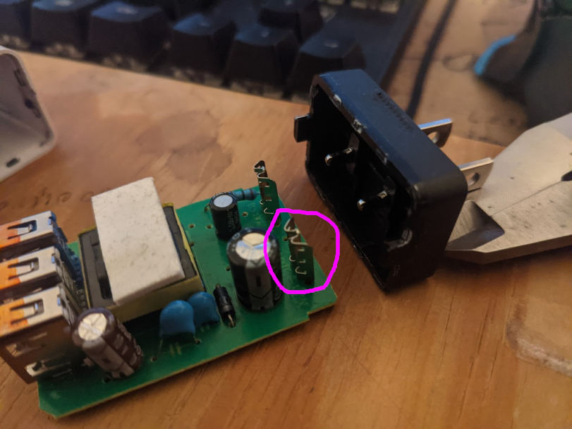
I've been scouring the internet trying to find an off-the-shelf part like this...

The part circled above it is a through-hole stamped part that makes contact with the blade connector, it's the power entry connector for the board. It's an extremely low-cost connector that has to be done right. If the component is to fail it could short against other components causing a fire. The component that actually plugs into the wall is custom as well and is "insert moulded" directly into the case itself. As I couldn't find any existing component I would have to draw one up myself, being new to FreeCAD and mechanical engineering I knew this one would be a challenge. Poking around enough, I found the Sheet Metal Toolbox to be the tool. This toolbox is for sheet metal, you lay out a flat design and add bends where you please. As a starting point, I desoldered a contact from the board above and flattened it out...
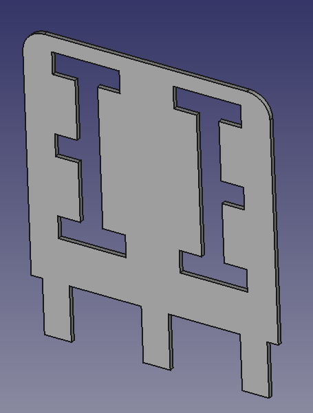
Then sketched it flat...

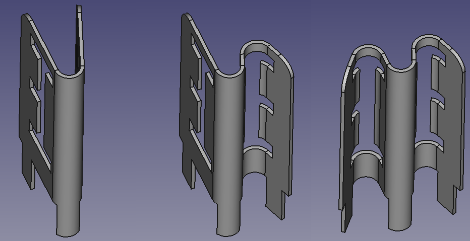
To make bends you sketch a line, then click the line and face. You define a bend angle and bend radius.

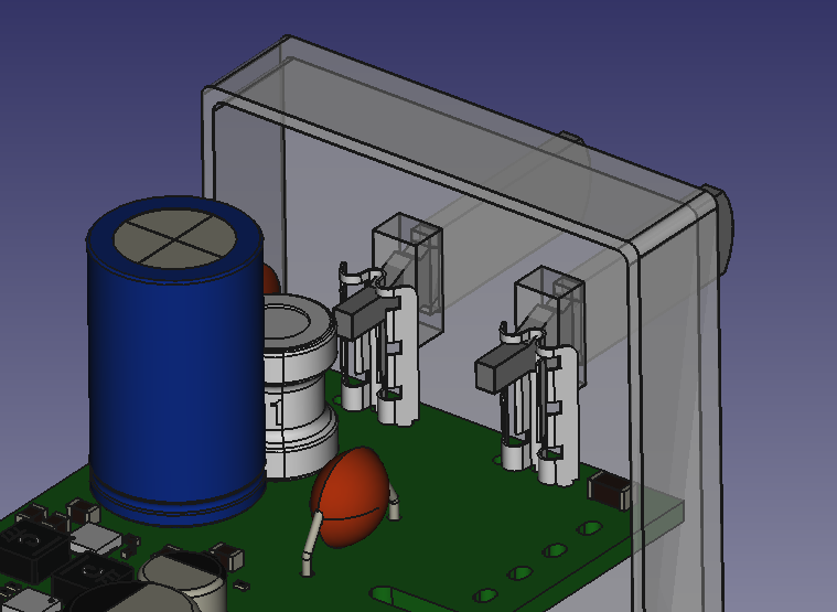
I then integrated it into the board file in Kicad exported a step file and reimported it into the FreeCAD assembly, there is still some alignment to be done but it's good enough for now.

Until next time ;) !
 Machinehum (Ryan Walker)
Discussions
Become a Hackaday.io Member
Create an account to leave a comment. Already have an account? Log In.