 zaphod
The display (this is the exact part used) is on the front of the clock and the main PCB is deep inside, and so some wiring needs to happen.
The display interface board is a little chunk of perfboard that connects wires coming from the display to the correct microcontroller pins, and sits right on top of the main board like so:
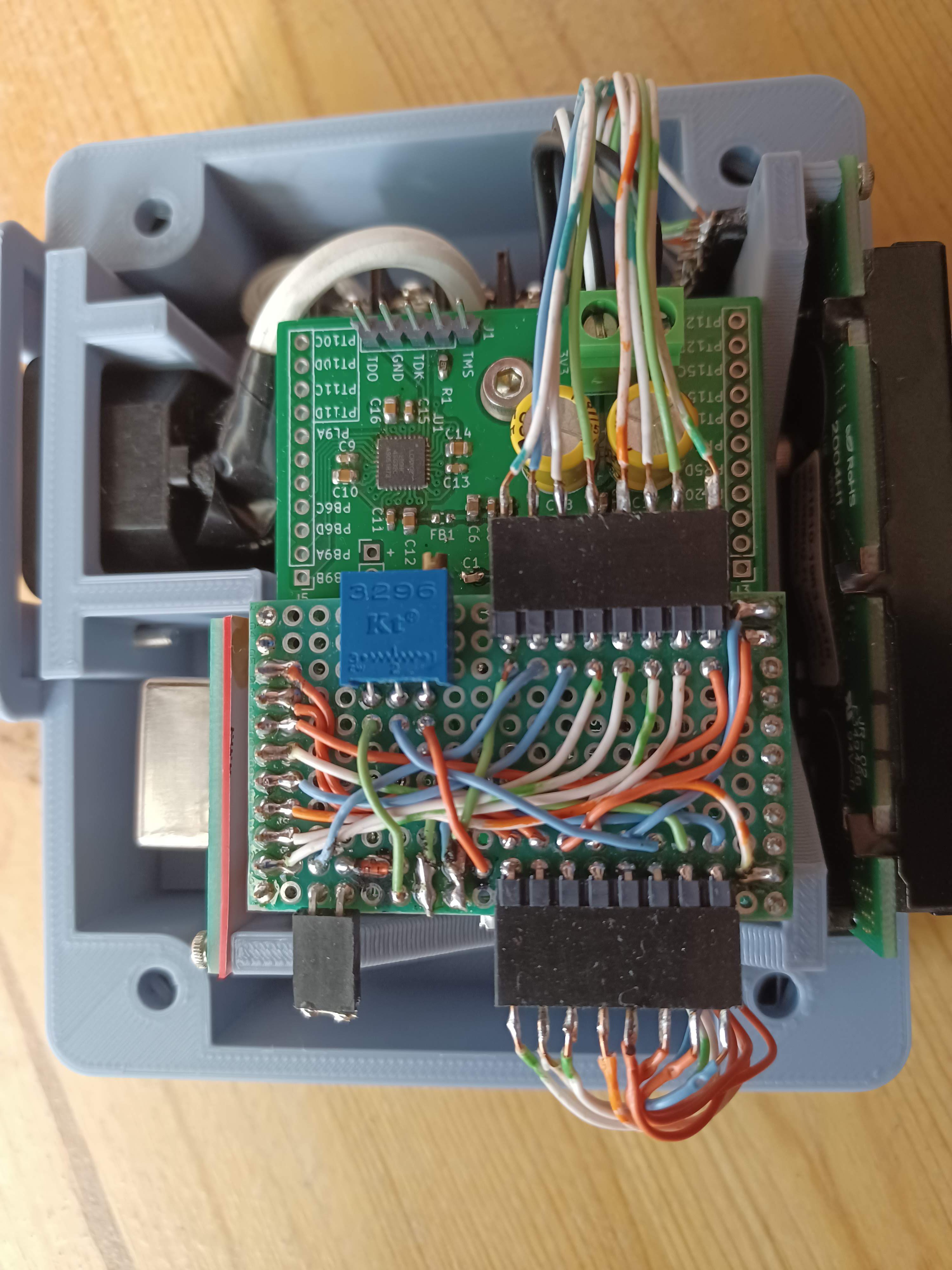
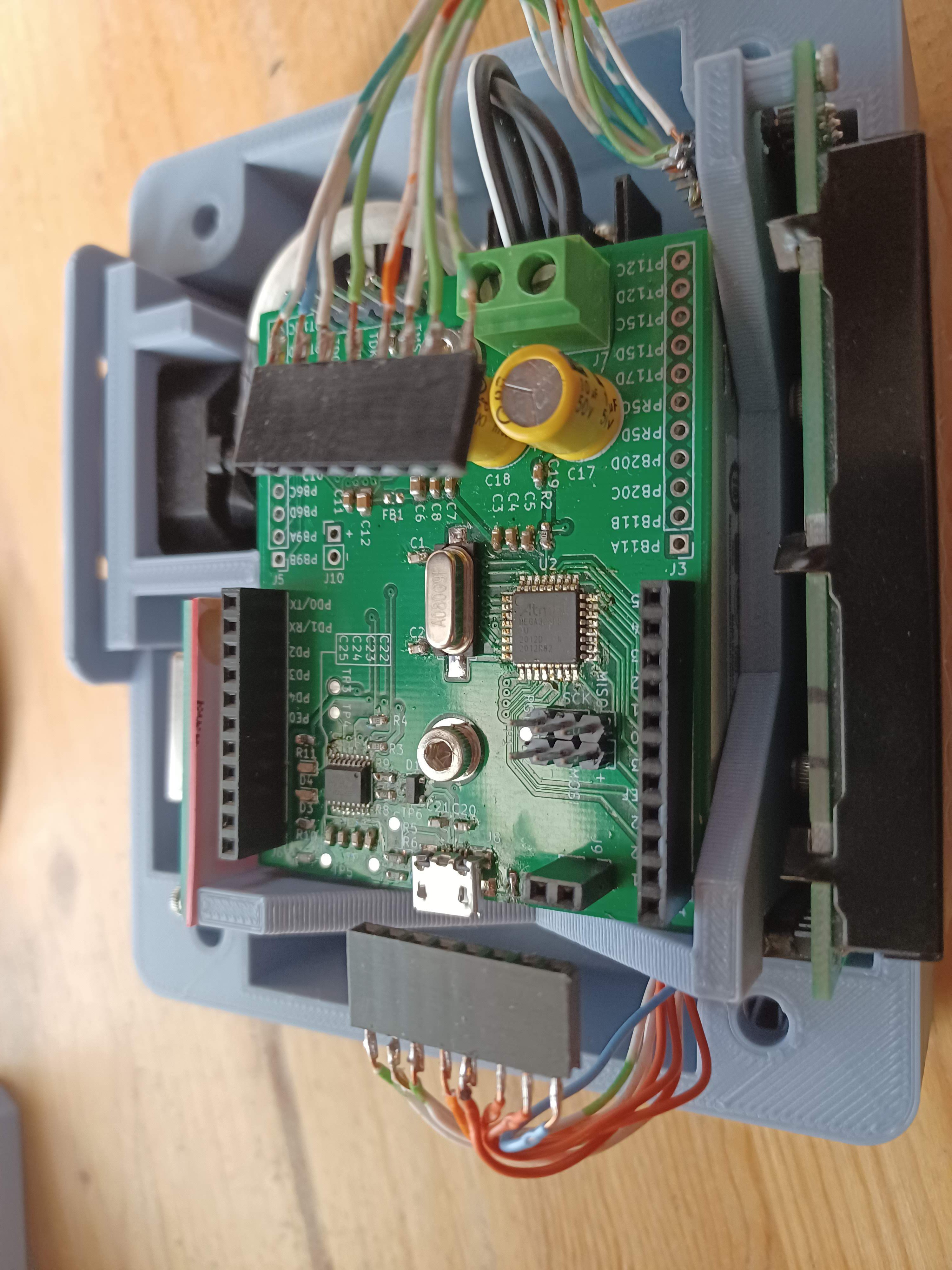
The board itself is very simple, it just has some wires, a trim pot, and a diode. The trimmer is used to set the display contrast, and the diode drops the 3v3 supply by ~0.7v for the display back light which is not rated for 3v3. Here's a pic of the interconnect board popped out of its socket:
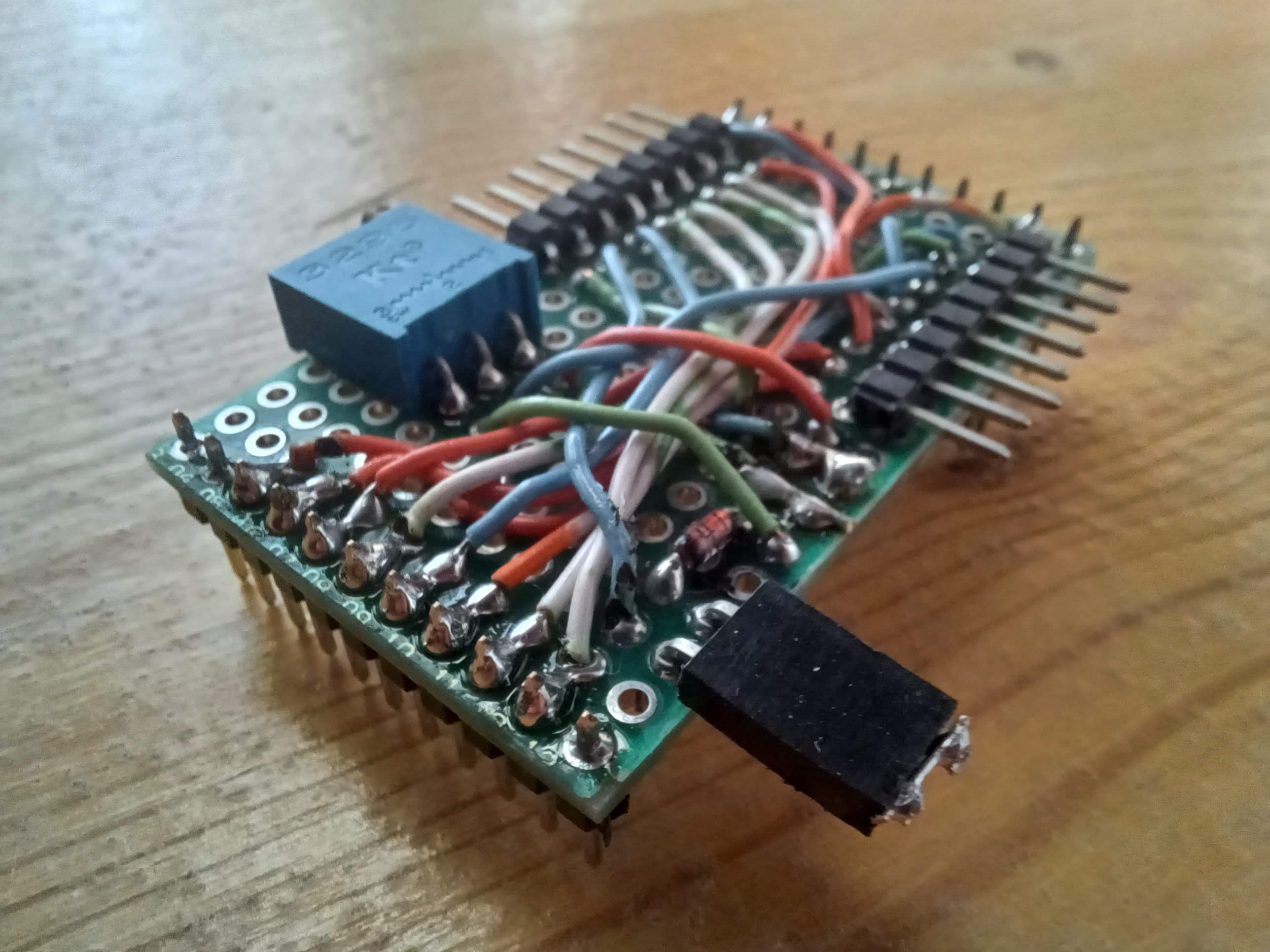
the shorted jumper is for the back light power, so that I can have it enabled or disabled. I might eventually connect the back light to something (switch or micro pin, etc) so I left a connector.
Since I'm probably going to have to order V4 boards for this project I might also make a pcb for the interconnect board, and the master oscillator carrier board, which are both just perfboard right now. we'll see.
Discussions
Become a Hackaday.io Member
Create an account to leave a comment. Already have an account? Log In.