The basic building block of the project is the WS2812 RGB LED. It's a popular part used in many projects in Hackaday, because it's chip and simple.
The interface is a serial one, with a DataIn pin and a DataOut pin for connecting them in cascade. Each LED will use the first 24 cycles, and shift the rest from DI to DO so the next LED in the line can do the same.
The period of each bit is 1.25 microseconds, and the duty will determine if it's a logic '1' or a logic '0'. A low level for 50 microseconds will cause the LED to update the colour value and start waiting for new pulses (reset condition).
The LED will show the same colour until a new value is shifted in and a new reset condition happens. There is no need to periodically refresh the pixels, unless they actually change. The time between these "changes" can be any long.
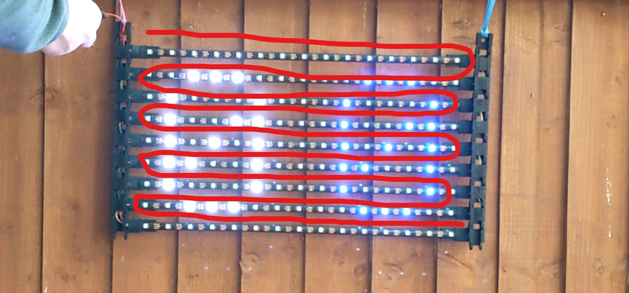
For this project, I used the IP65 strip, 5m length and 30 LED/m. As the resolution is 15x9, I have to cut each strip into 10 sections of 15 LED each, keeping the last one as spare. Sections are chained, to simplify the electric wiring, causing the data to go like a snake across the display. That way, only one pin of the MCU can drive the whole display (data flow is indicated with the red line in the image)

Because each LED needs 24 bits, and there are 135 LEDs, the total time for shifting all the information is
(24*1.25µS)*135 + 50µS = 4100µS = 4.1 mS
That's quite reasonable, even for driving the LEDs in "bitbang" mode, which will basically block the CPU for manually toggling the input pin.
 LordGuilly
Discussions
Become a Hackaday.io Member
Create an account to leave a comment. Already have an account? Log In.