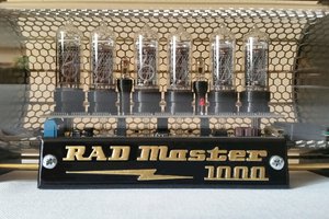
CAUTION !!
Please do not try to replicate this unless you really know what you're doing.
The high voltages both AC and DC are very dangerous ! Be very careful and do not attempt to start a project like this if you're a beginner. You have been warned !
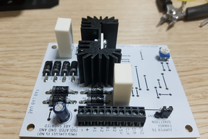
The power supply has a dual voltage DC output, 16V and 220V. I used two small footprint transformers to step down from 220VAC to 12V and then step up to aprox. 160V. After rectifying I got to 220VDC which is needed to light up the nixies.
The 16VDC is stepped down to 5V using a buck converter, and it's used on the driver board.
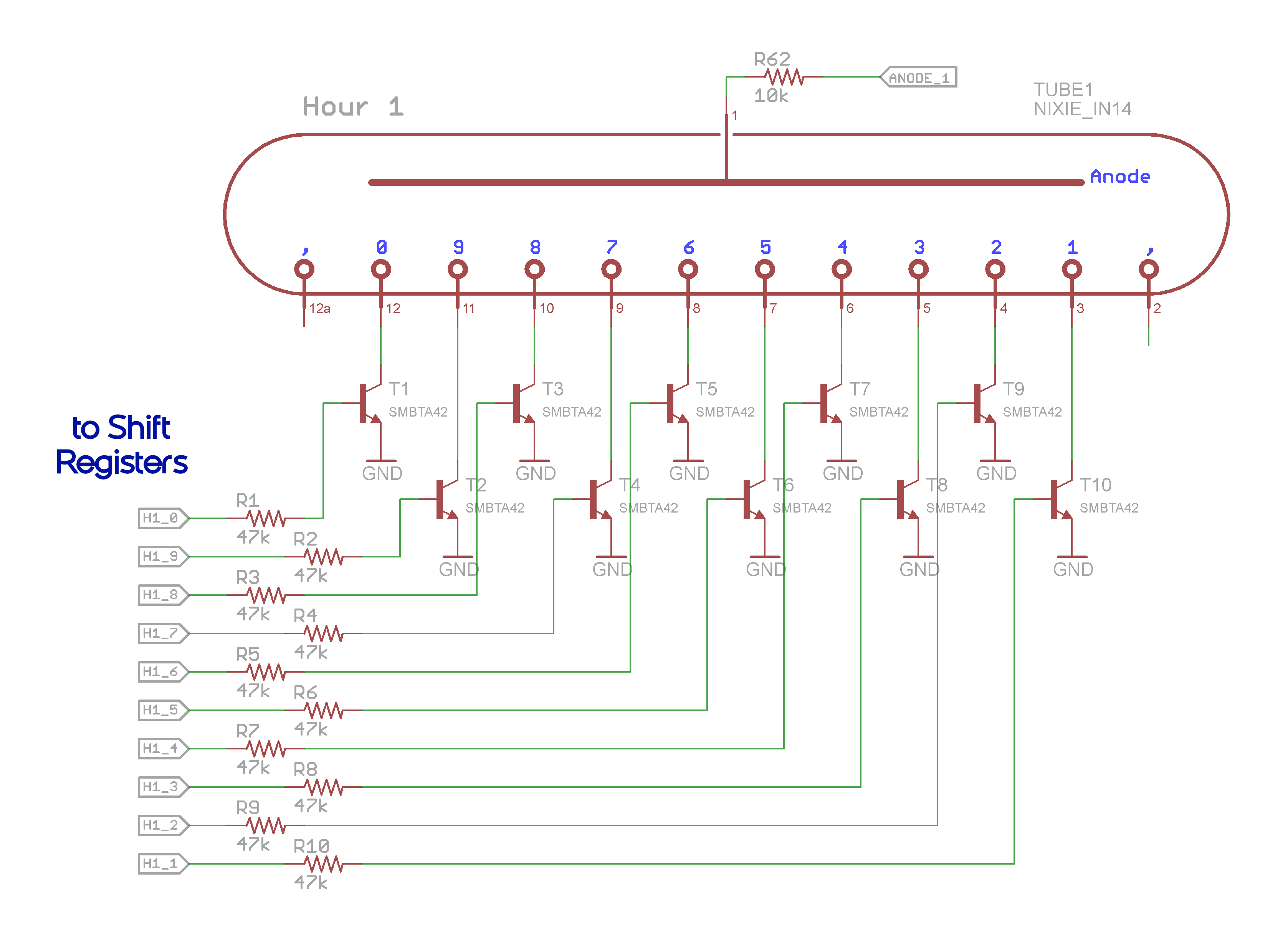
To drive the nixies I used High Voltage transistors (SMBTA42). Each digit (cathode) is driven from daisy chained shift registers. I can pulse width modulate the anodes of the tubes to modify the brightness.
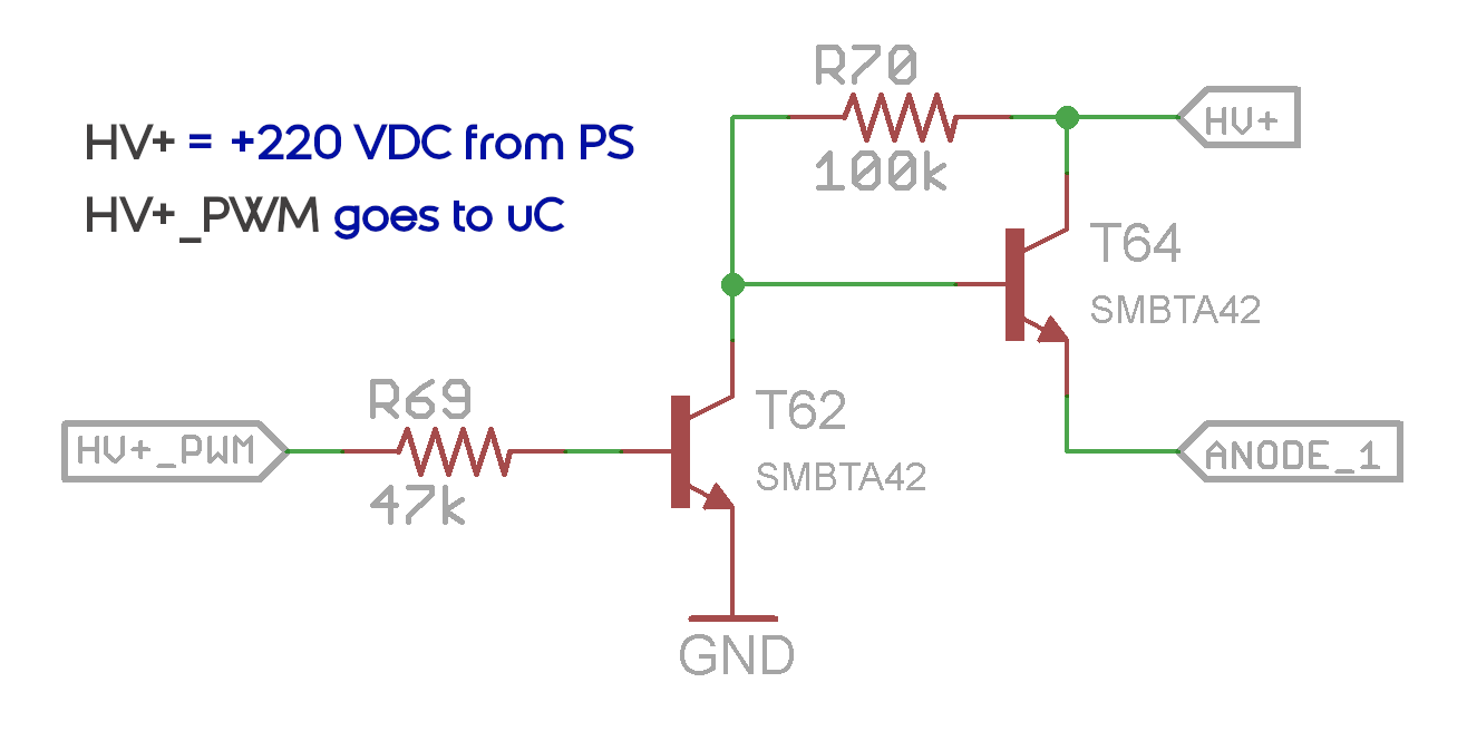
There's a RGB led under each nixie tube. I have 8 base ambilight colors and a random loop - color changing sequence.
The clock is based on the DS3231 RTC, and it's very precise and battery backed up. I've also implemented an alarm and I'm using the microcontroller's EEPROM to write and read, pretty much all of the settings (useful in case of a power loss).
Everything can be manually controlled or using an IR remote control.
For the case design, I started with some rough sketches, and then started to 3D model everything.
Besides the 3D Printed parts, I used brass, steel, and glass for fabrication. The hexagonal grid does not have any functionality. I just thought it looks cool.
If you like this project check out my Youtube channel - Designing Hardware for other tutorials and builds.
 core weaver
 Gabriel D'Espindula
 nrrdzilla
 Arya
Arya