 teru
teruChanged battery voltage measurement to measure input of voltage regulator battery voltage measurement using circuit from https://jeelabs.org/2013/05/17/zero-powe-battery-measurement/. Also display battery level on the clock screen.
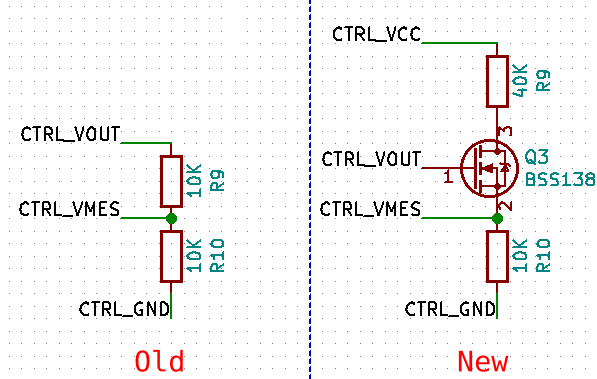
Previous version measured voltage output from GPIO pin so value is capped to 3.3V, which was enough to see if battery is too low but not so nice for displaying battery level.
Fortunately it wasn't hard to modify - replace resistor between Vout and Vmes with BSS138, connect drain of BSS138 to new resistor, and connect the other side of the new resistor to vcc.
Unfortunately, measurement didn't work. It shows greater value than correct voltage. Modification was worked fine when tested with develeopment board. It turned out that ADC of the ESP32 of the clock seems to be broken. The adc pin reads as almost 0 as expected when connected to GND, but the adc pin reads as 4095 (maximum of 12bit) when it is left open.
Discussions
Become a Hackaday.io Member
Create an account to leave a comment. Already have an account? Log In.