Close
0%
0%

3D Printable 2-axis MEMS Mirror

A home buildable 2D mirror for controlling light deflection.

Similar projects worth following
MEMS mirrors are great for use in Lidar devices and for laser-projection displays. They provide a method of steering a laser significantly more rapidly than moving the entire laser itself, allowing for faster scan rates. Trouble is, these mirrors are rather expensive (>$400, not including the mirror's controller/drivers boards), so acquiring one would certainly blow the budget for a project that needs one.

The goal of this project is to try to create a 2-axis mirror that can be created at home or in a maker space that is capable of achieving similar specifications to manufactured ones (deflection angle, max scanning rate). Ultimately, I would like to use one of these as a CRT-like display, eliminating the need for high-voltage drivers and using tubes that are (unfortunately?) no longer manufactured.

There are a few stages to the overall project:

Stage 1: Build the Mirror System (MEMS Mirror Part) - In Progress

This entails creating a mirror device that can deflect a laser beam with a relatively high scan rate with some degree of repeatability and accuracy. Parts needed for this are the mirror itself, the gimbal, the system for deflecting the gimbal, and a driver for the gimbal deflection.

Stage 2: Add a Screen (Creating a CRT-like display)

The second stage will make use of the mirror gimbal system developed in stage 1 to create a CRT-like display. Ideally, the system will be able to display vector graphics (like those in Asteroids Deluxe). Currently, the plan is to use a UV laser to excite some form of phosphorescent screen to give the system a glow reminiscent of a CRT.

Stage 3: Video Input (Tentative)

If the display is performing well and appears to be capable of performing raster scanning, I may try to implement some form of composite or VGA video decoding/input. This may take the form of keeping up with the incoming video signal and displaying it as it comes in or potentially grabbing a single frame every few seconds and using a long-persistence phosphor to allow the system to slowly raster out each frame.

  • Custom Drivers Underway!

    Ray Clemens06/14/2021 at 02:09 2 comments

    [June 2ish]: Since the car stereo was designed for audio, there is a bunch of DC-offset removal from the output that is not desirable for controlling the mirror. As a result, it was time to build my own coil drivers.

    Most of the time spent in the design for the drivers was determining if I could buy a COTS power supply that could provide the amount of power I needed in a dual rail configuration. From my estimates and data collected from the bench supply, I would need about 8A on a +/- 15V supply. This makes it infeasible to be constructed out of linear regulators due to the amount of heat that would be dissipated. The other challenge was that finding negative voltage switching regulators with such a high current capacity proved very difficult. In the end, a single-supply design was settled on due to its simplicity and my realization that I might be able to use two symmetrical drivers in a differential scheme for coil driving. Here, the drivers are a mirror of each other around the VCC/2 voltage.

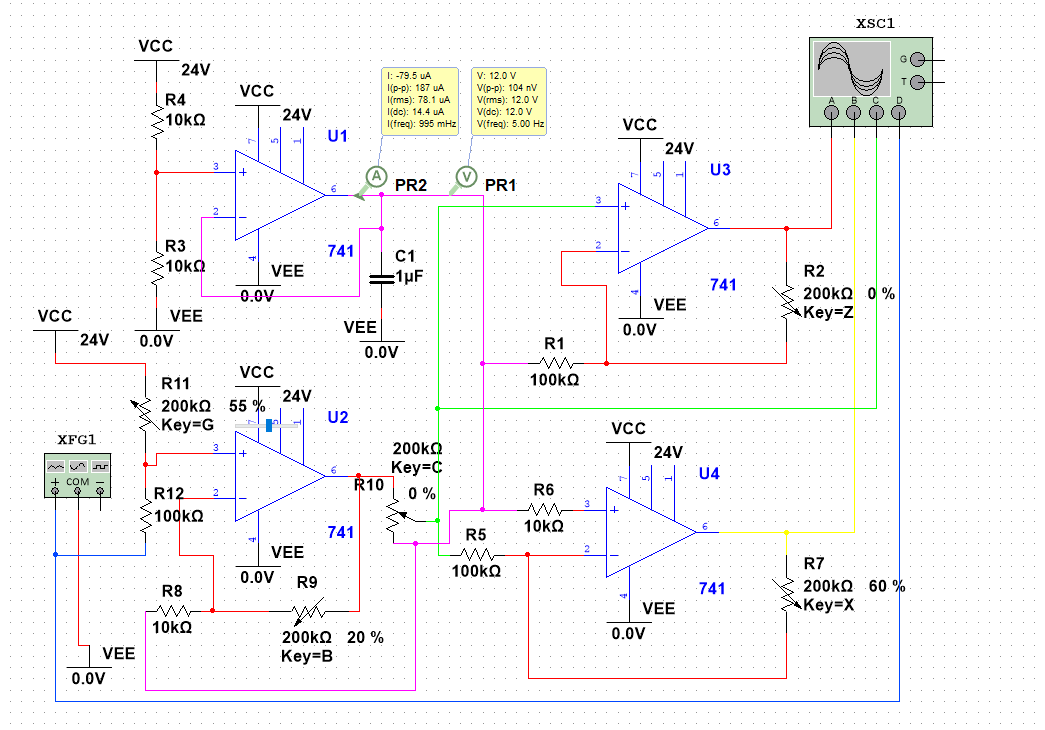
    A few hours in a circuit simulator later, I had a tentative design worked out that only required four opamps and worked off a single, variable supply.

    In the above schematic, XFG1 is the output of the DAC and XSC1 is reading the output voltage of the output amplifiers. (The finalized KiCad schematic is on GitHub)

    I transferred the design into KiCad, added the DAC, some extra regulators for the digital side, routed the board, and sent them off for production. A quick note about the DAC: I went for a parallel-interface unit (DAC7613E) instead of one that operates over a serial bus like SPI since I wanted the system to be easily controllable from old 8- and 16-bit computers (in case someone wanted to use this as a display for one). Also, the parallel interface allowed for me to use pullup resistor networks on the pins, making it easy to only use some bits of the DAC if all 12 bits are not needed.

    Pretty soon, I'll have these boards built up and see how they perform!

  • Rocking out to Sine Waves

    Ray Clemens06/14/2021 at 00:52 0 comments

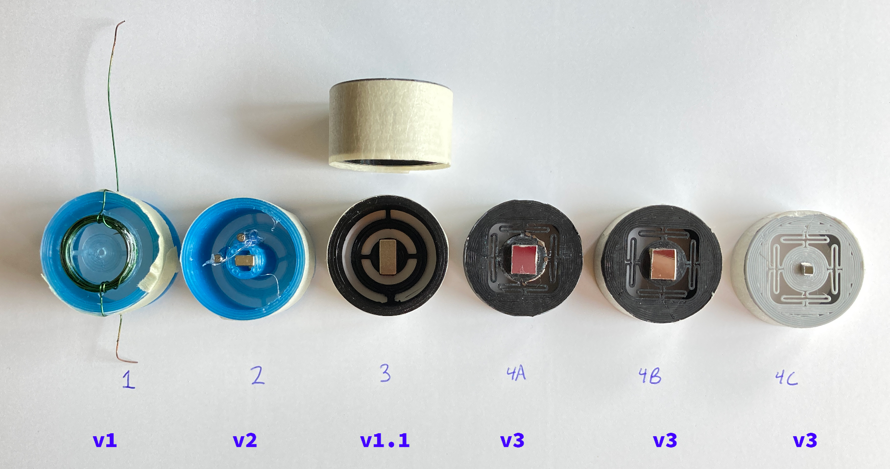
    Lots of progress! By about May 29, the above set of gimbals had been developed (with the help of lots of online searching for commercial MEMS mirror designs). The top row of hand-written numbers is the trial number and the bottom row is the gimbal design version. Going in order:

    Gimbal 1 - After trying out different nails in the original gimbal design, I decided that the amount of deflection was not going to be as high as I would like. As a result, I took a slight detour and decided to move the coil onto the gimbal and place some magnets on the outside, similar to a motor made with some wire, paperclips, and a battery. The result? Less deflection than the nail inside the yoke, while reintroducing the overheating problem.

    Gimbal 2 - I had the realization that by adding magnets to the gimbal, the yoke's force exerted on it would increase because of the field interactions. This design uses two rectangular neodymium magnets fitted into a cylinder under the gimbal (picture is a bottom view). The magnets increased the deflection slightly. To see if adding some metal to the gimbal would help "guide" the magnetic field at all, two nails were hot glued to the outside of the cylinder, parallel to the magnets. This helped tremendously.

    At this point, I figured it would be a good test to see what kind of frequency response I could get out of this setup. Since the coil impedances of the yoke (2 and 4 ohms, depending on the coil axis) were similar to that of a typical speaker, an old car stereo was hooked up to drive both the axies. With a waveform generator on my computer (A.K.A. Audacity and onlinetonegenerator.com), I tried out different frequencies of sine waves and found the resonant frequency of the gimbal setup to be around 10Hz. This was much slower than I had hoped, but it was still progress.

    It was time to find a mirror for the gimbal, and I knew just the place to get it: the platter of a dead HDD. Taking the Dremel to the platter, I produced a ~6x7mm square which got taped to the gimbal via some rolled masking tape. Combined with a laser pointer, I was able to move the point around with a few inches of deflection at about 5 feet.

    Gimbal 3 - In an effort to increase the resonant frequency, I printed another gimbal and this time, used the same rectangular magnets from the second revision. One magnet was placed on either side of the gimbal's central disk and the mirror was stuck to the outside. This new gimbal sandwich gave improved results, providing a better deflection angle and a higher resonant frequency of about 50Hz. One downside to this configuration is that the two axies seem to interfere with each other when there is a rapid change in the yoke's input waveform (i.e. a sawtooth wave). This produces a lot ringing in the reflected laser beam.

    (Gimbal 3B) - [Not pictured] Two of the 10mm-diameter magnets (used in 4A) were used to create a sandwich, similar to 3. In the process of feeding the yoke a sine wave, I turned the amplitude up a bit too high and turned the gimbal into a small motor, rotating the magnets around and around for about 10 seconds before the plastic broke. Oops :)

    Gimbal 4A - A single, round neodymium magnet was superglued to the bottom of the gimbal disk while a mirror (and some of the table top) was glued to the top of the gimbal. The gimbal design was modified to use "O" shaped springs (found in here), allowing the axies to interfere less, reducing the ringing and providing a nearly identical response out of both axies.

    Gimbal 4B - Similar to 4A, however, the large, 10mm-diameter magnet was changed out for one of the previous rectangular magnets that was cut in half to give a 5x5mm magnet. After cutting the magnet, I found that the side that was in the vice still had a strong magnetic field, while the half in open air had about the level of a fridge magnet. Looks like the heat of the cutting process caused some demagnetization. This was the most promising of the gimbals so far, with a resonant...

    Read more »

  • CRT Yoke to the Rescue

    Ray Clemens06/14/2021 at 00:03 0 comments

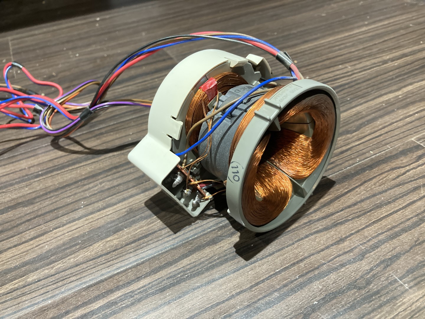
    A friend of mine was getting rid of a projection TV and asked if I could come over to help dismantle it to get it out of his basement. Excited to tear down his TV (and get some lenses), I headed over and after about an hour, we had a pile of electronics and a pile of wood and plastic.  I got to take the electronics home and while I was unloading everything, I realized that the deflection yokes from the CRTs were designed for the sort of task I was trying to solve.

    Don't these look like Podracer engines?

    With the yoke in hand, I did some quick 3D modeling to create a 30mm diameter 2-axis galvanometer to fit in the center. To make sure the gimbal had a tight fit inside the yoke, the outside was wrapped with about one and a half turns of masking tape.

    In the small hole in the center, I put a small nail to give the yoke something to act on. Connecting one axis of the yoke to the bench supply, I was able to get about 1-2 degrees of deflection out of the gimbal. Despite operating at around 2-3 amps, the coils did not get terribly warm, even after a few minutes of adjusting the current. This new setup seems to have the heat problem solved, so now on to getting more deflection out of the gimbal.

  • Single Axis Deflection Design Tests

    Ray Clemens06/13/2021 at 23:14 0 comments

    Note: I'm writing these updates a little while after I actually completed each update, so I think this update was from around May 22.

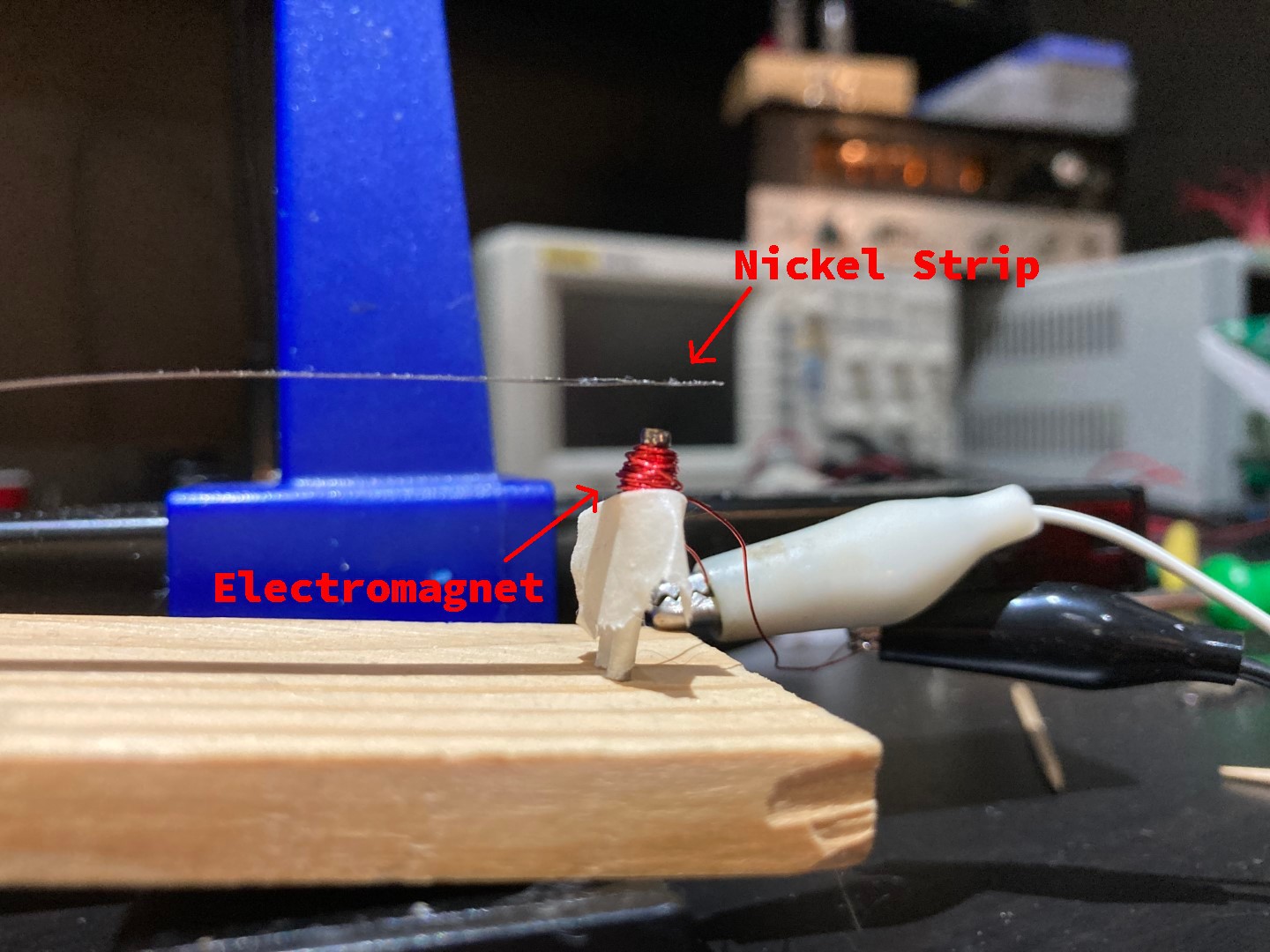
    Anyway, the first thing I needed to figure out was how to get something that is very small (2-3mm diameter) to move and eventually to control its position. From the preliminary research I performed, it appeared that MEMS mirrors are electromagnetically or electrostatically driven. (I later found that one company uses bimetallic strips to thermally deflect their mirrors as well). The electrostatic actuator idea was set aside after some quick electrostatics calculations and the decision to keep the operating voltage as low as possible. With electromagnetic deflection the only other choice, I built up a small test rig:

    As seen above, the rig is a nickel strip which is actuated with an electromagnet. The hope was that if this worked, then it might be possible to polish the nickel to a mirror finish, producing a 1-axis mirror.

    Throughout the testing of this setup, it quickly became apparent that this setup had a few flaws:

    • The nickel strip liked to bounce a lot when the electromagnet was turned on or off.
    • The amount of current needed to drive the tiny coil was causing it to heat up very fast (and start smoking in one instance).
    • The distance between the nickel strip and the electromagnet had an impact on the amount of attractive force, meaning that motion was highly nonlinear.

    Some of these issues could potentially be resolved:

    • The strip's bounce might be able to dampened through the use of a hall sensor and a feedback loop to a microcontroller. (Although I did not have any hall sensors on hand)
    • The coil current and heating issue could be resolved with a larger coil.

    These potential improvements ended up not being implemented, however. The magnetic field idea still seemed promising, but it was not until trash day the following week that I had a breakthrough...

View all 4 project logs

Enjoy this project?

Share

Discussions

Similar Projects

Does this project spark your interest?

Become a member to follow this project and never miss any updates