 Kevin Santo Cappuccio
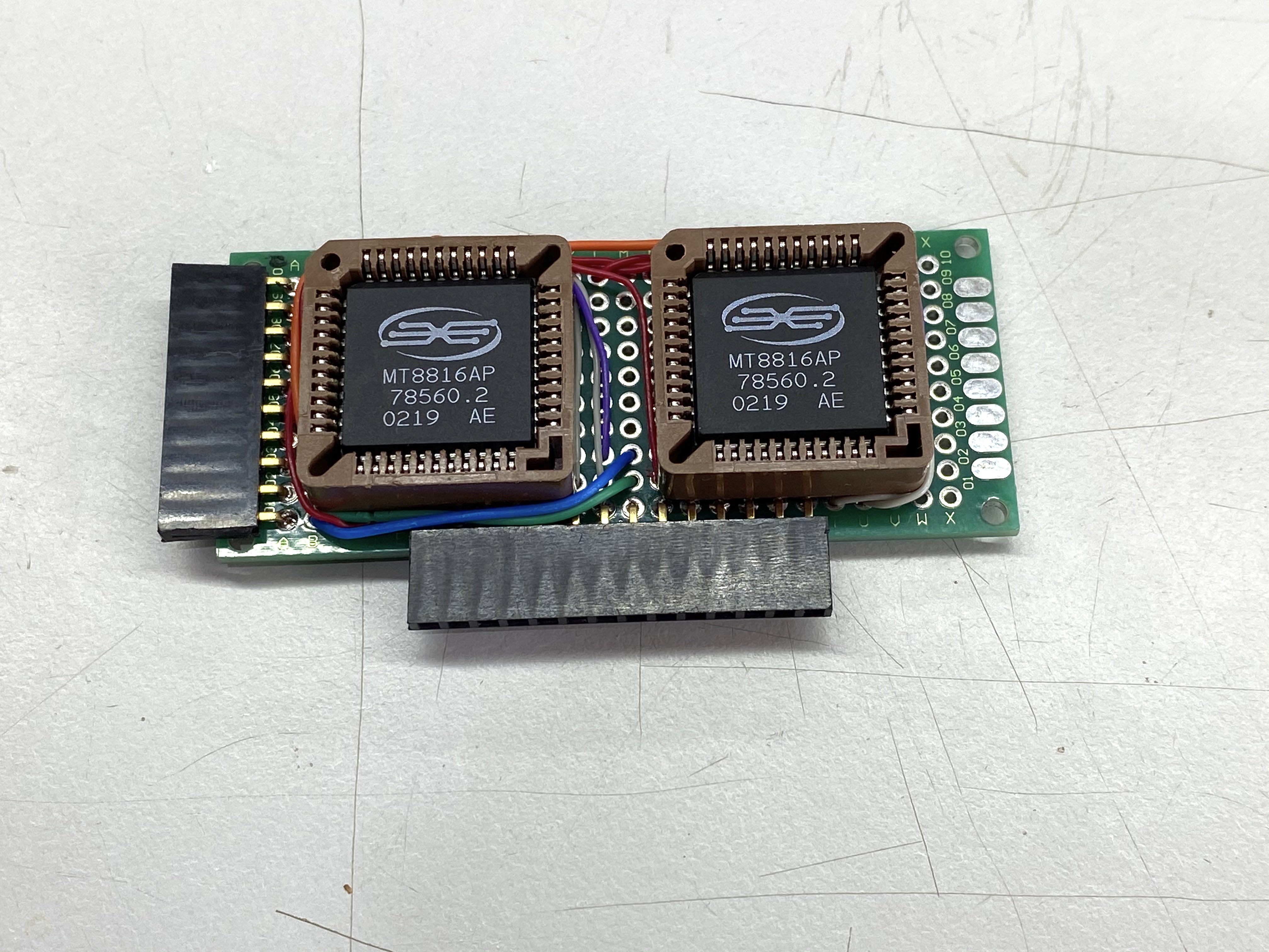
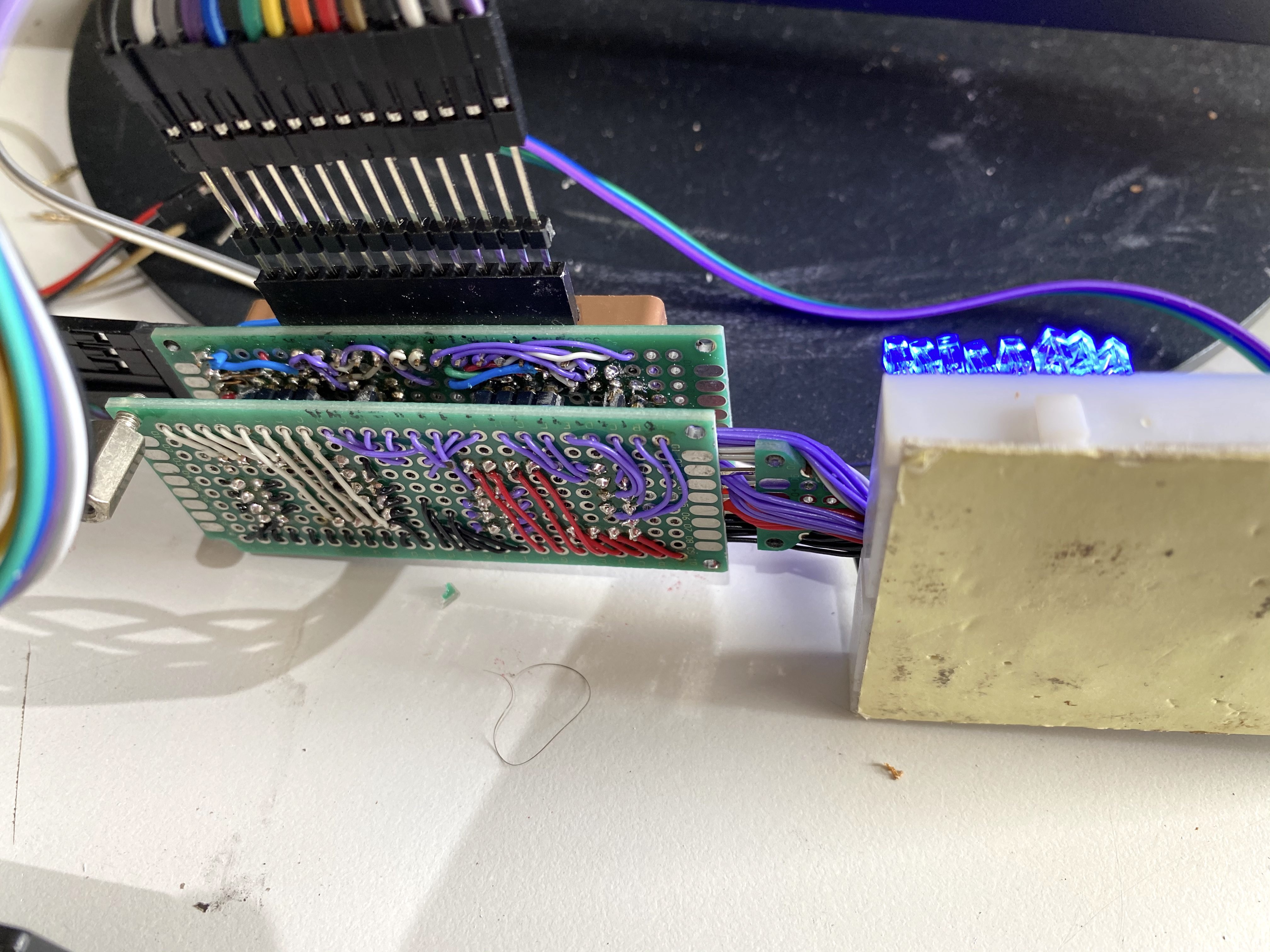
After seeing that a single MT8816 would work, I wanted to make sure you could route a connection through 2 of them and still have a reasonably good connection. Because using a single 32x32 crosspoint wasn't gonna happen, I think they actually might exist (it's been a while since I looked into it), but they're in the few hundred dollar range per chip, and they're generally for HDMI switching so they don't really have the qualities you'd want in a general purpose analog switch.
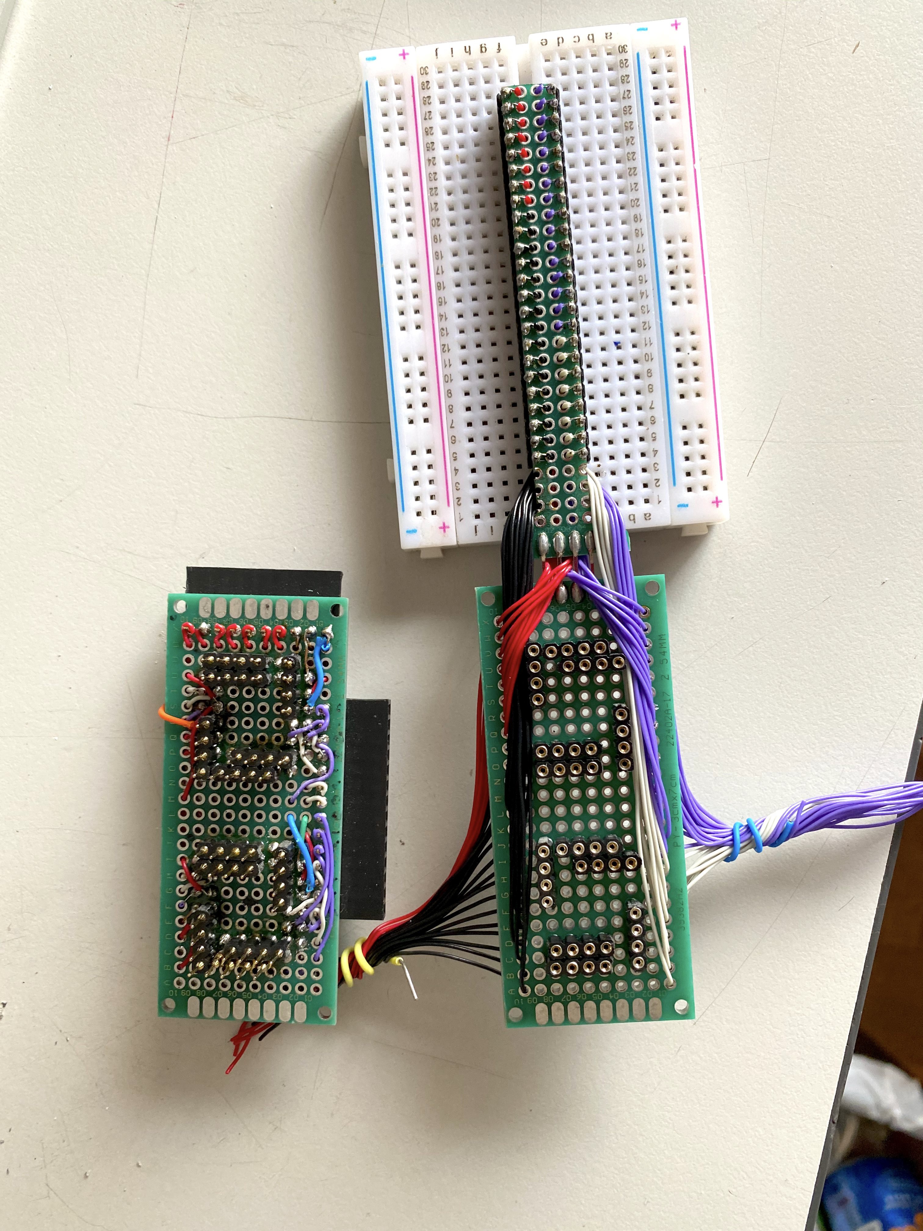
I also wanted to make it not take up the whole breadboard so I could actually test it on real things.
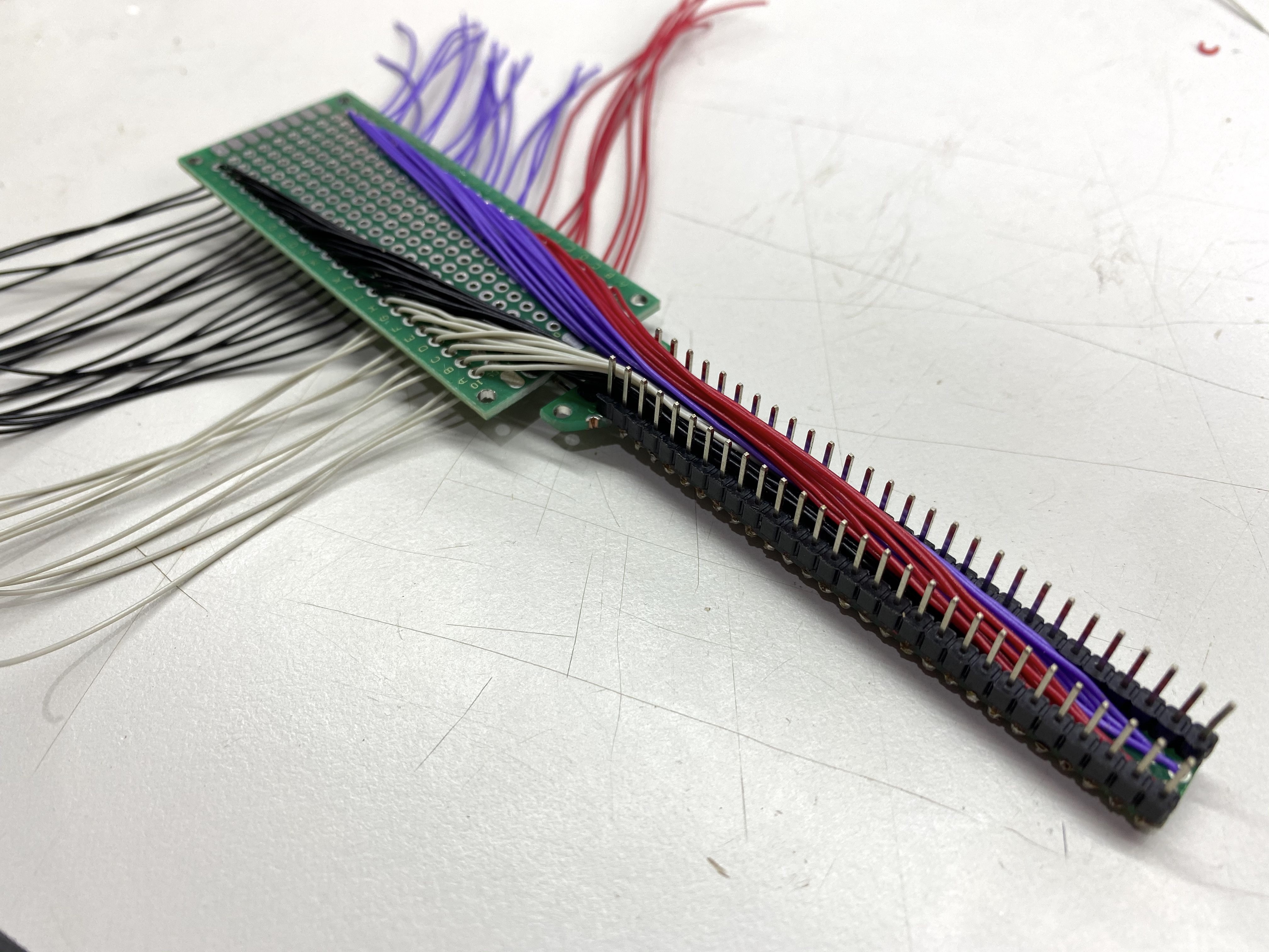
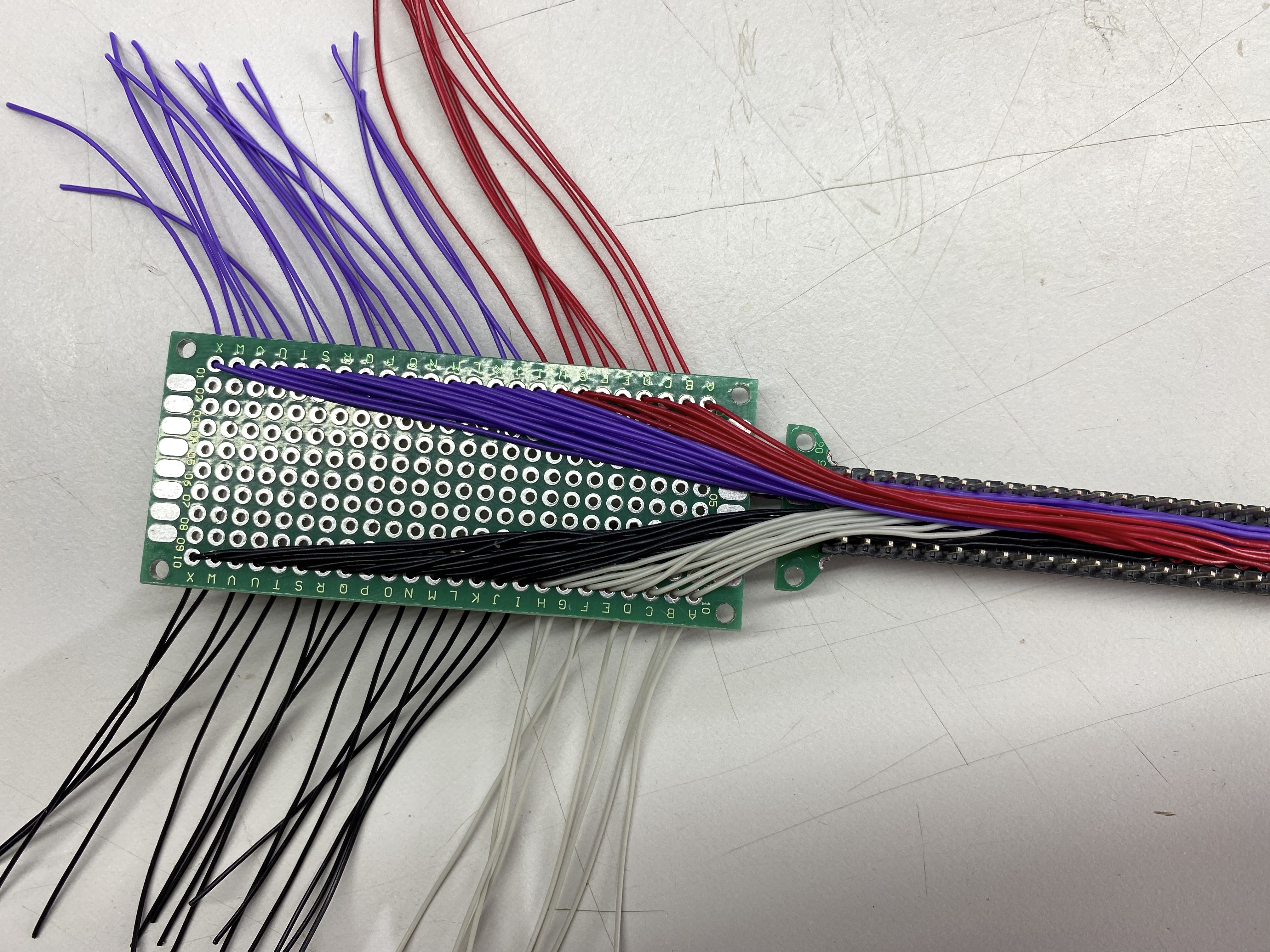
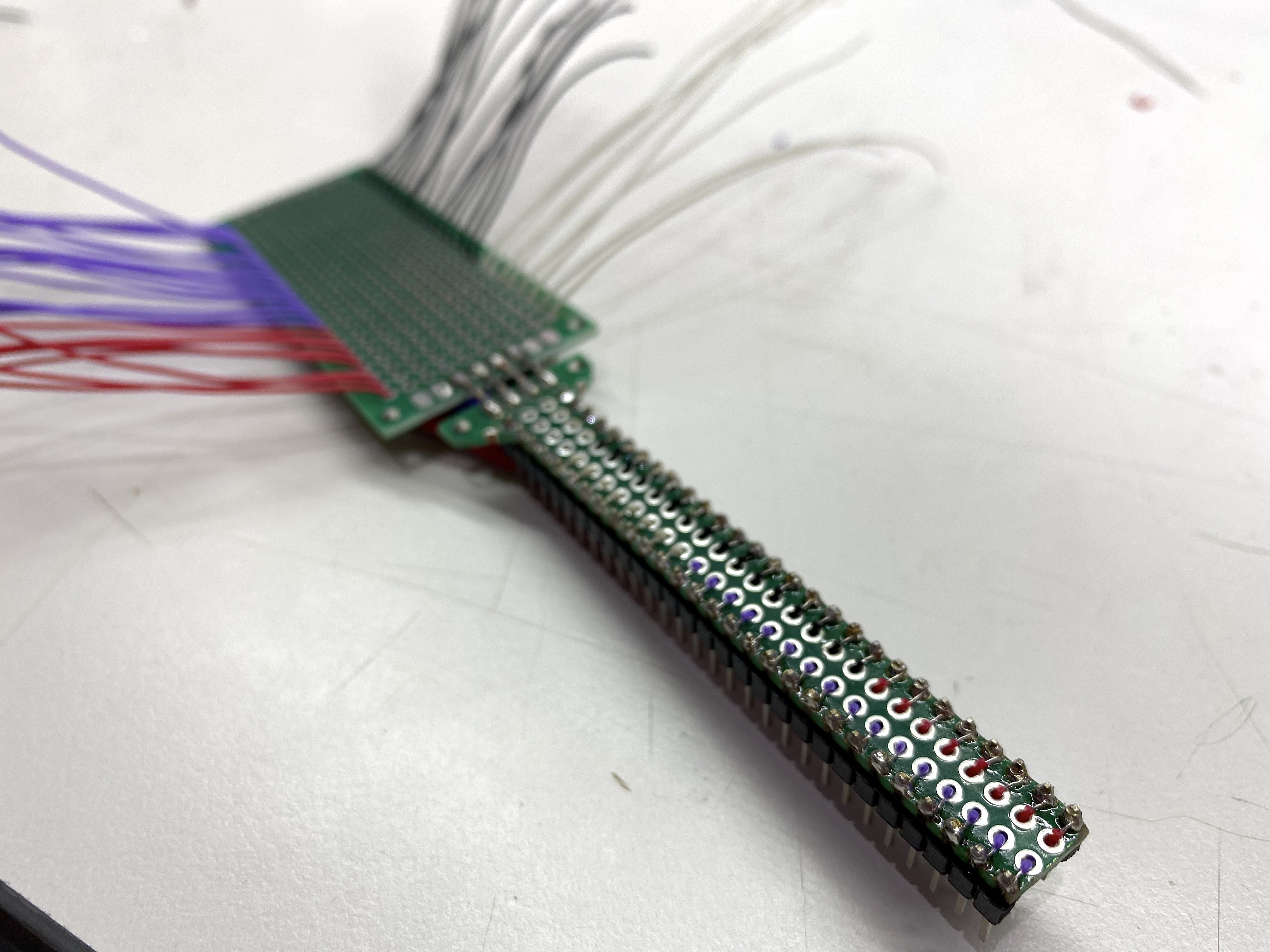
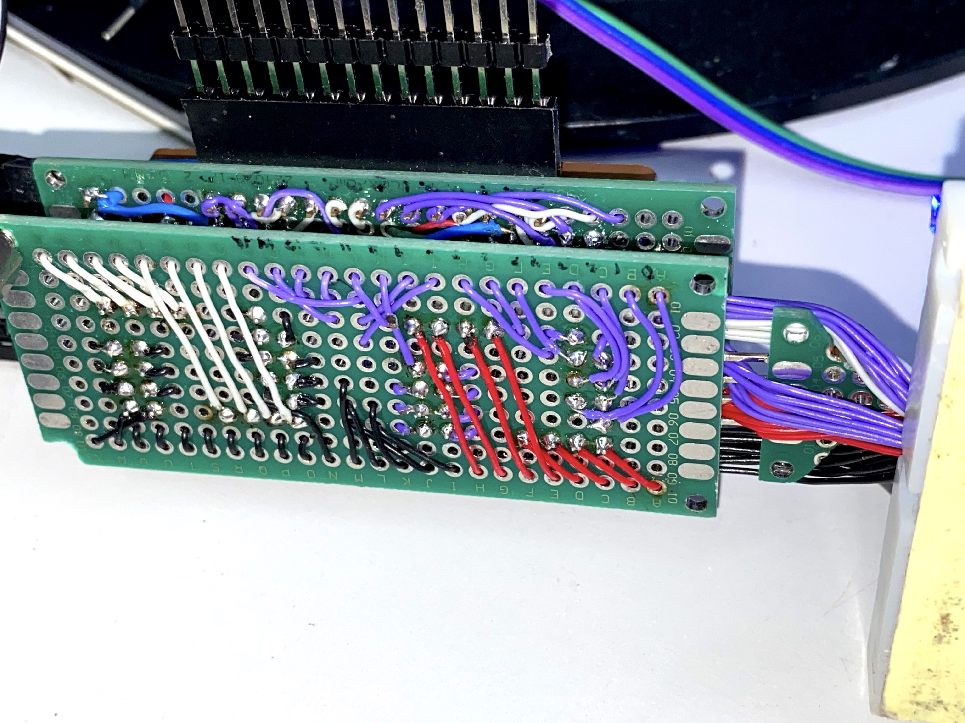
Disclaimer: what I wrote above is a lie, the real reason I made this is because I had just discovered the joys of wire-wrap wire and I needed an excuse to use it.
What follows is basically a slideshow of me building this thing.
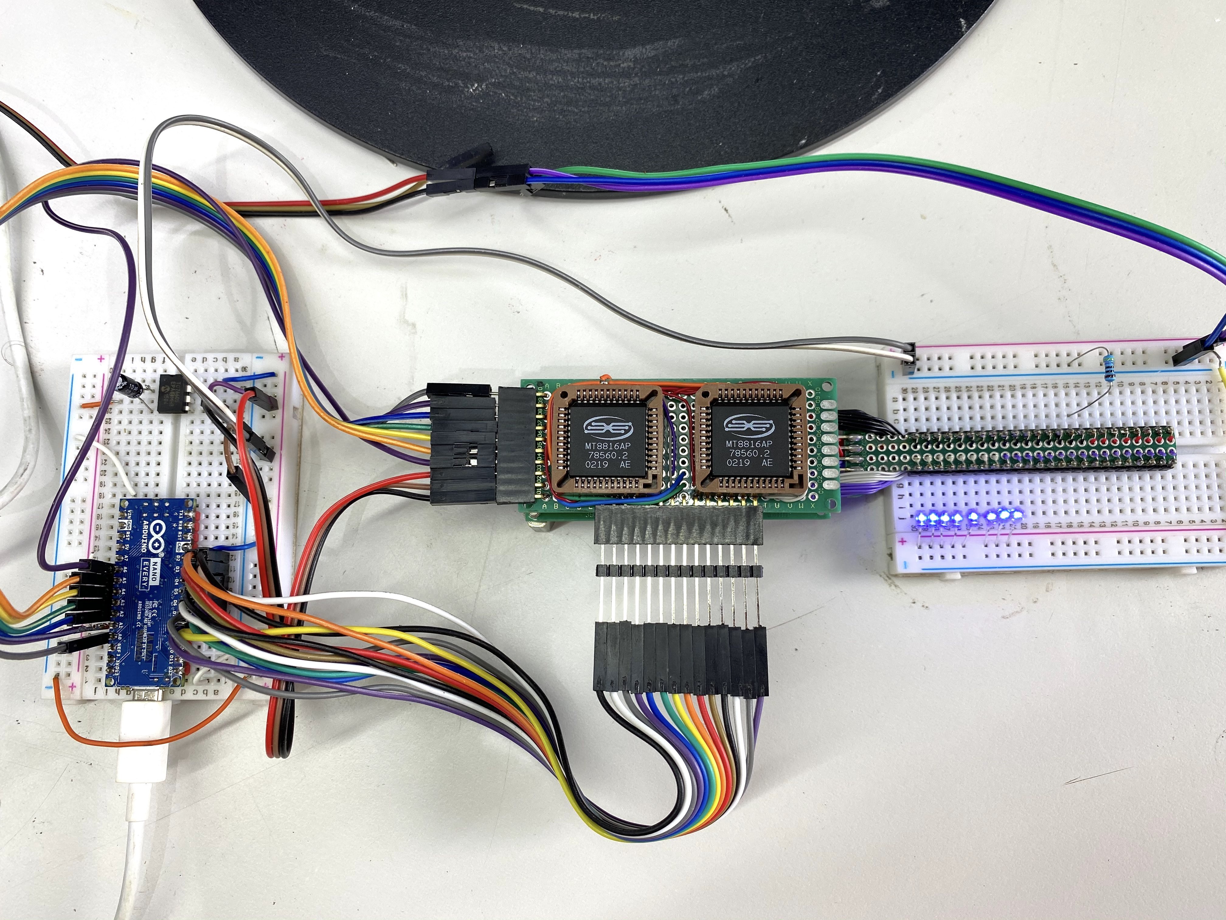
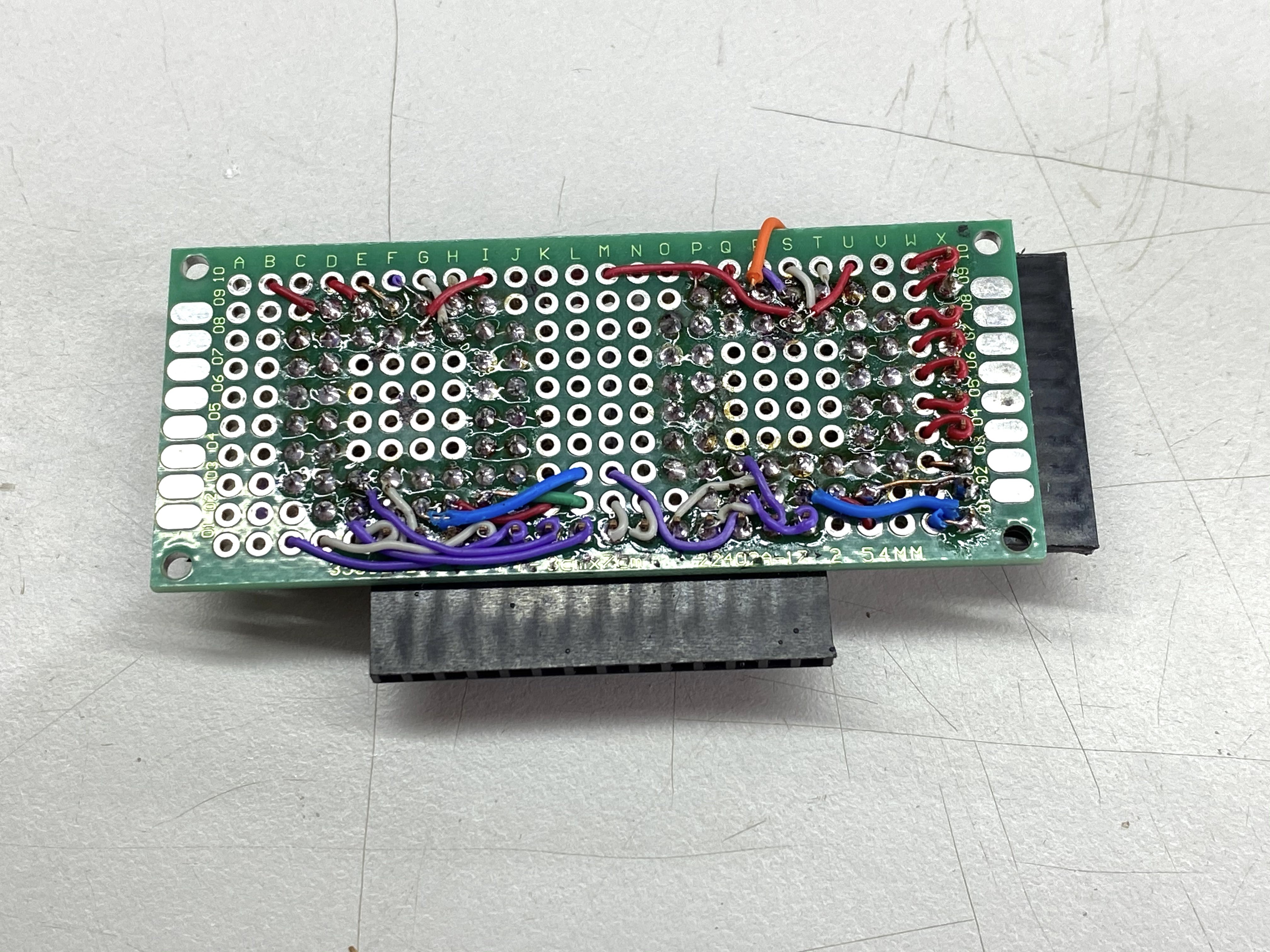
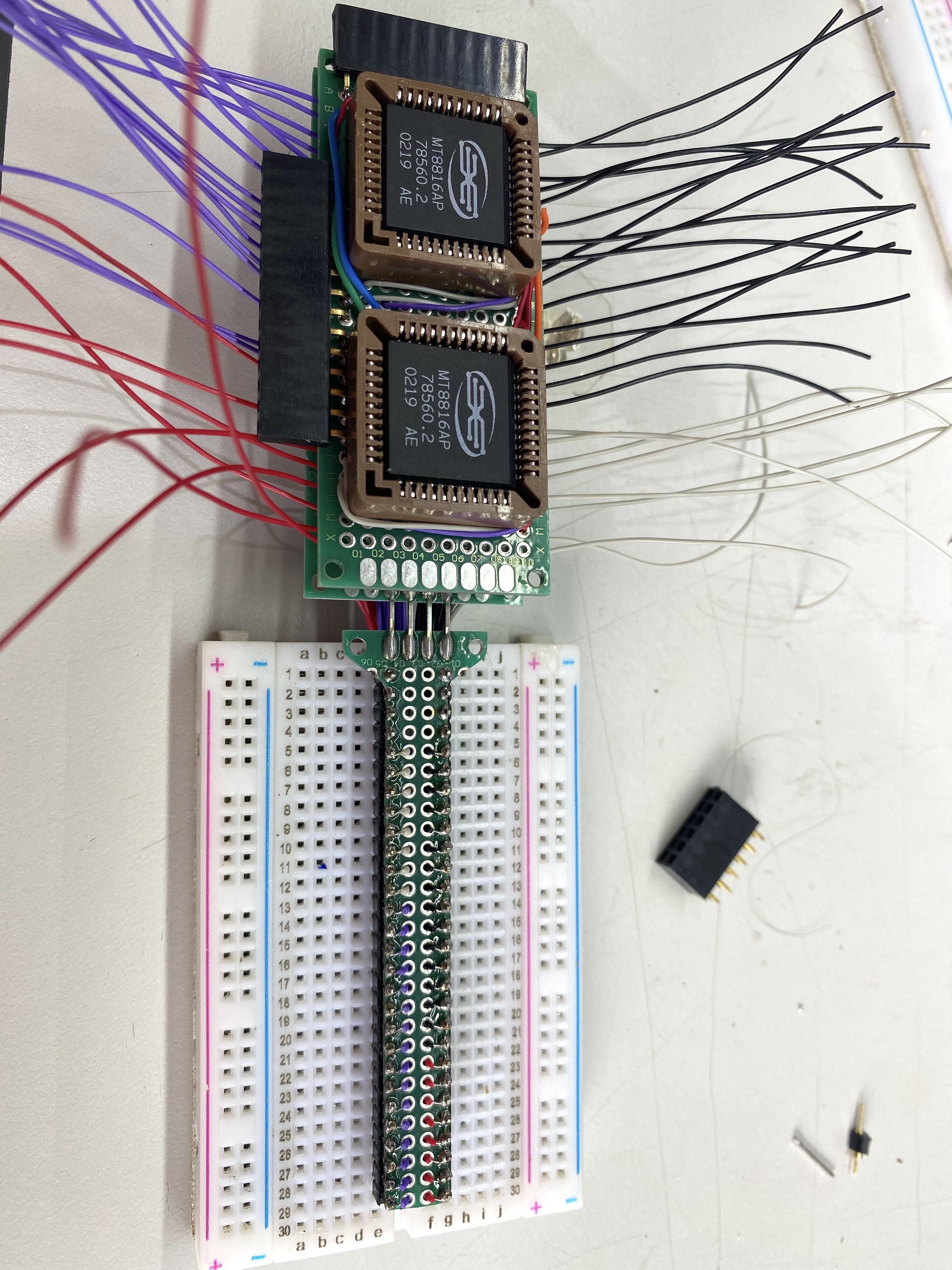
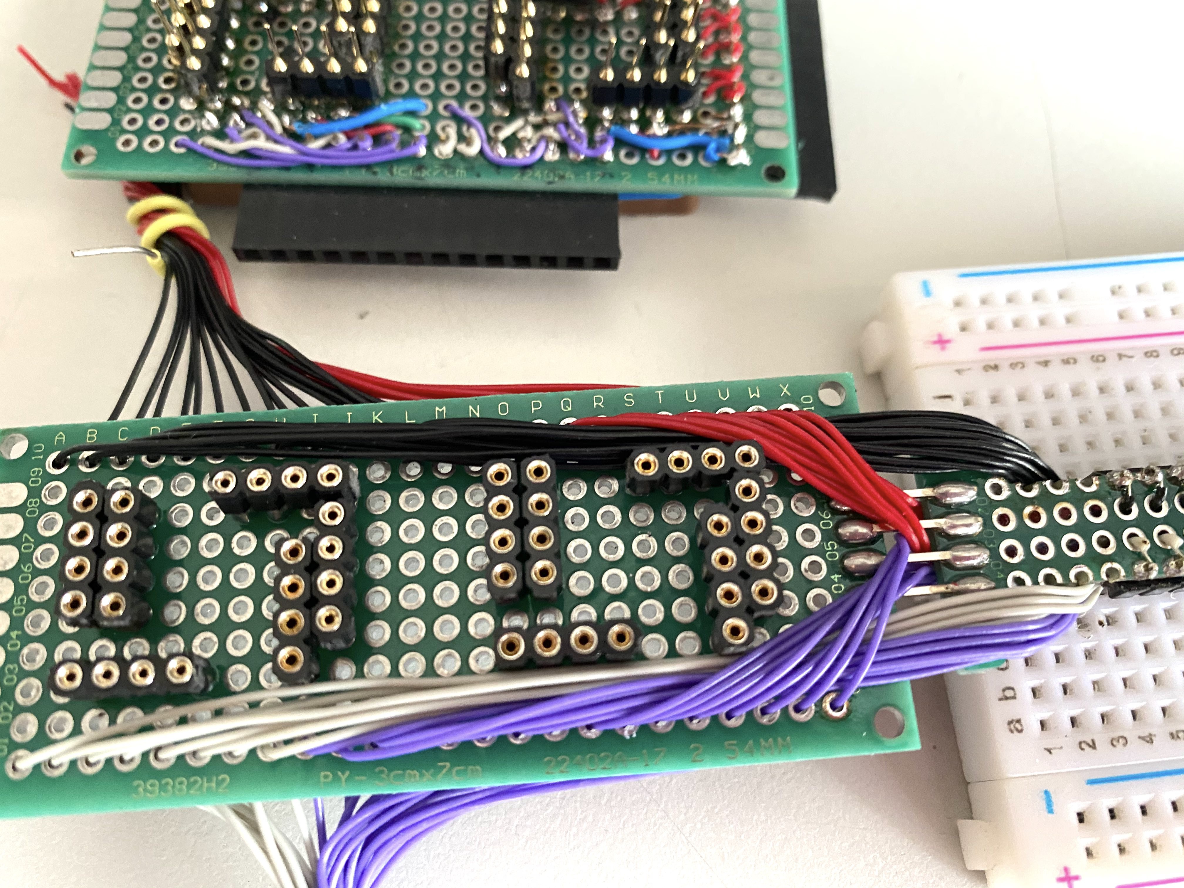
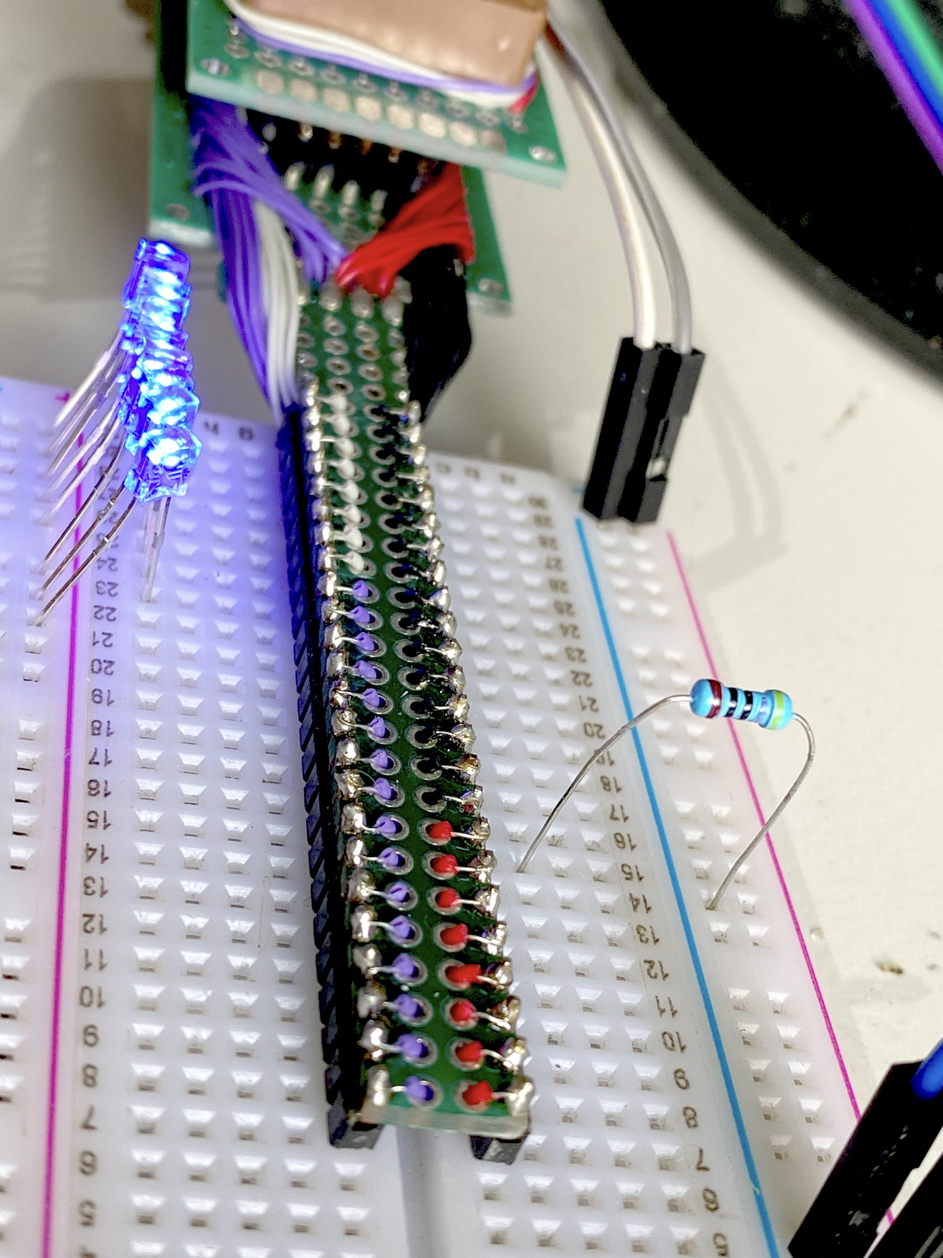
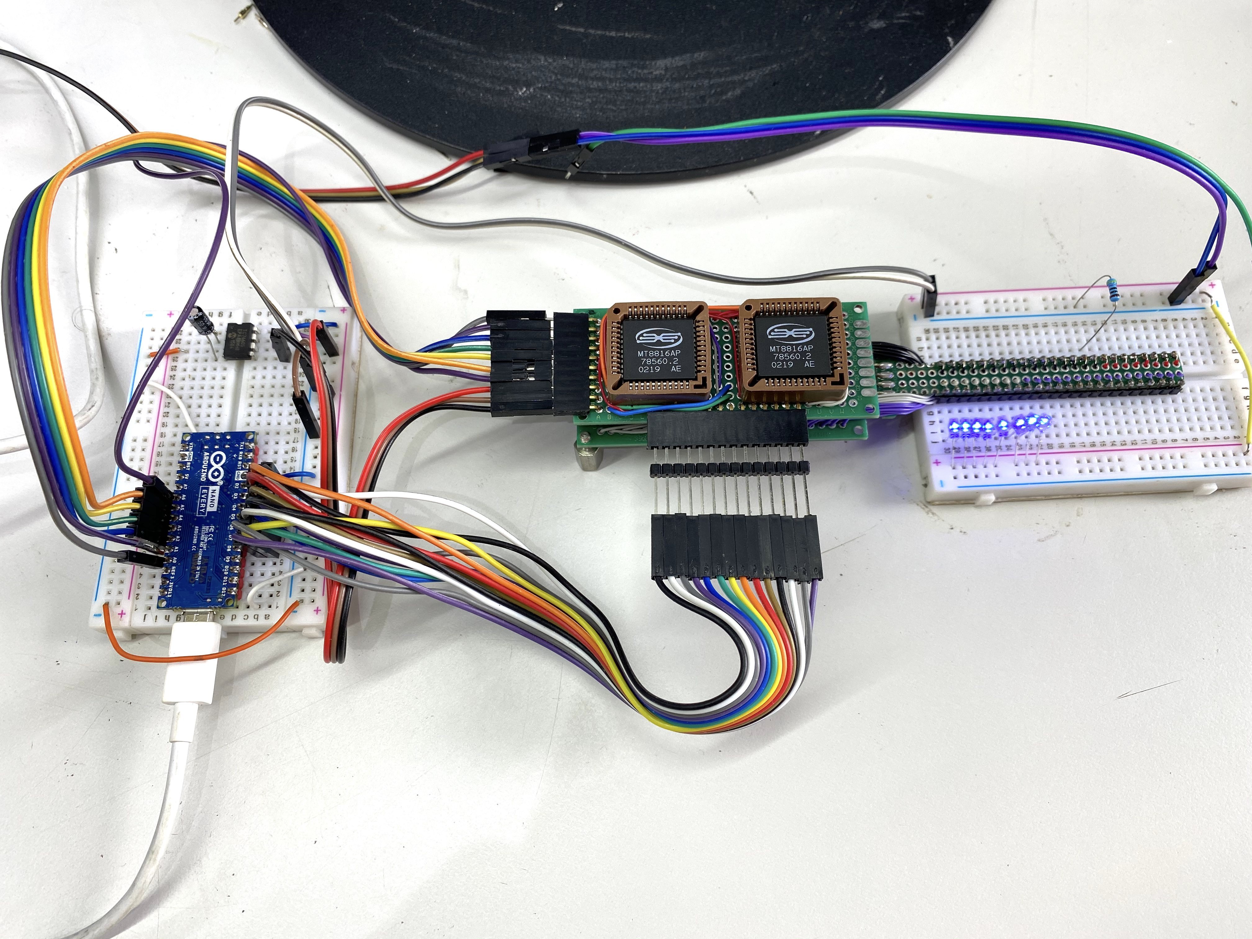
This is the pinout for the rows of wires going to the Arduino Nano Every
Control Lines (top to bottom) (left side of board)
CS A
DAT A
STB A
RST AB
CS B
DAT B
STB B
Vdd +
Vss GND
Vee -
Address Lines (left to right) (bottom of board)
Y0 A
Y1 A
Y2 A
X0 A
X1 A
X2 A
X3 A
Y0 B
Y1 B
Y2 B
X0 B
X1 B
X2 B
X3 B
Discussions
Become a Hackaday.io Member
Create an account to leave a comment. Already have an account? Log In.