 Kevin Santo Cappuccio
So it's been a while since I actually did anything on breadWare, but it's always been in the back of my mind and everything I've worked on since has been helpful in figuring out how I should approach this next revision.
I haven't routed any traces yet so it's easy to change things, so if any of you Hackaday people see anything wrong (or even if you think something could be better) I would love to hear your armchair engineering.
Here's a list of the things I changed from version 2:
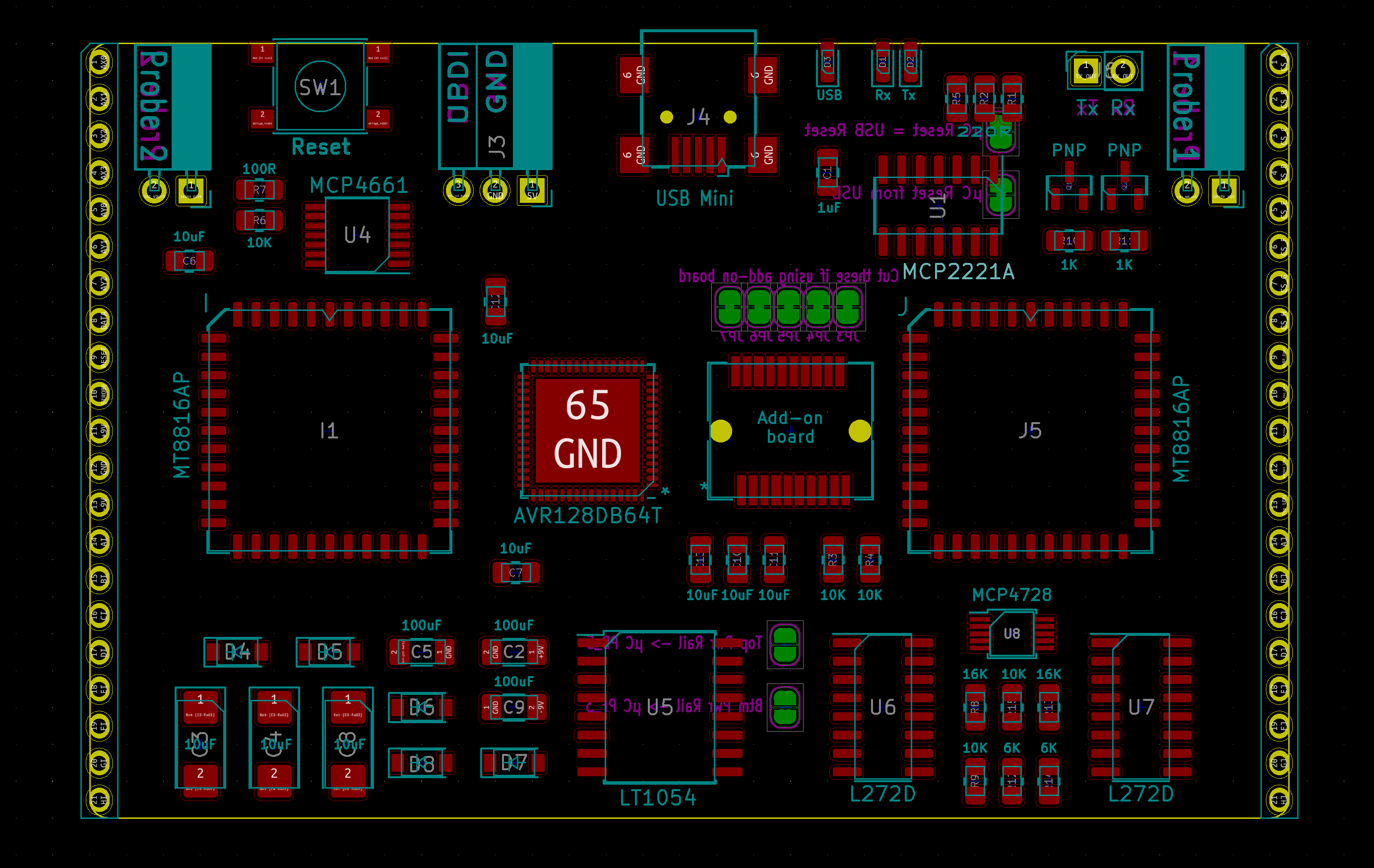
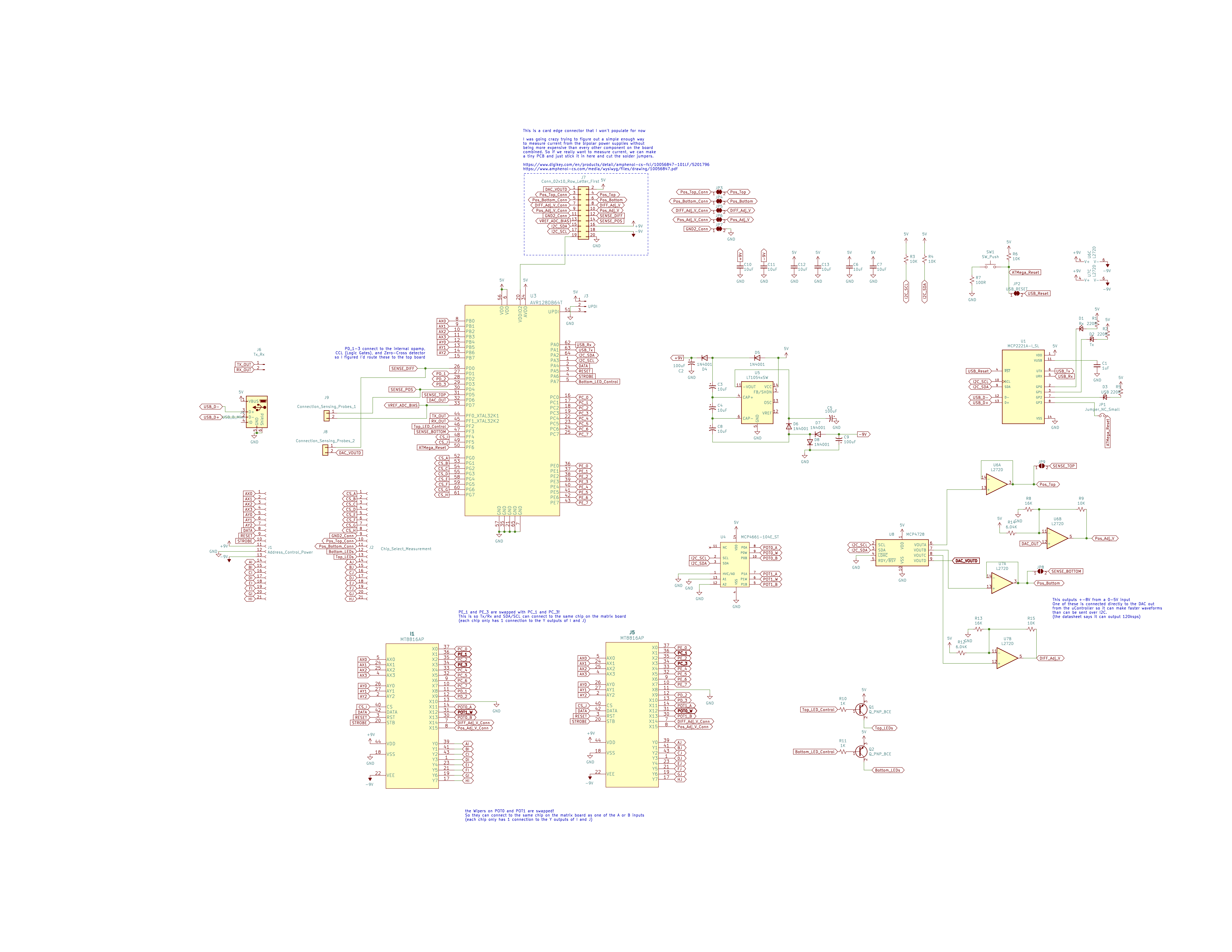
- I'm using an AVR128DB64 as the microcontroller instead of the ATMEGA "Every-tool-just-kinda-forgot-to-support-me" 4809. I've been way into these new series of chips Atmel has been coming out with. And having all the documentation from https://github.com/SpenceKonde/DxCore is super nice. [Spence Konde] and [MCUdude] deserve a frickin' Nobel Prize.
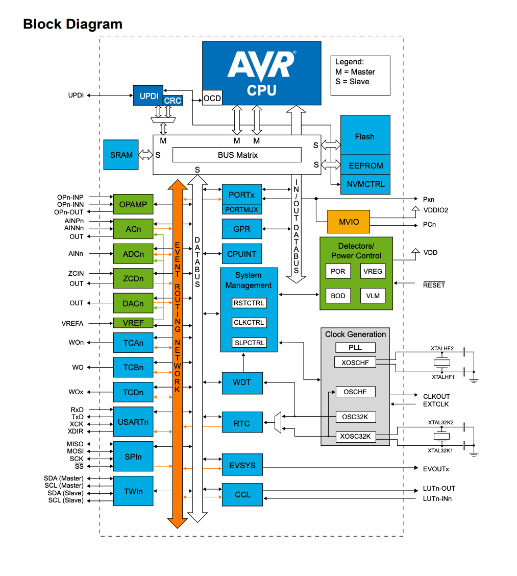
I managed to get a good deal of those peripherals on the left side connected to somewhere you can actually use them on the breadboard.
- Every crosspoint switch is connected to every other one on the board directly (but now there's only 2 direct connections between each chip) and the 2 extra connections are each connected to the 2 (instead of one) special function chips on the control board. I'm pretty sure this is a better way to do it than Version 2 but most of the problems come out when writing the code to handle the connections. So instead of spending too much time trying to guess every pitfall beforehand, I'm just going to try it and see where the new problems arise. (Once again, suggestions will be lovingly welcomed)
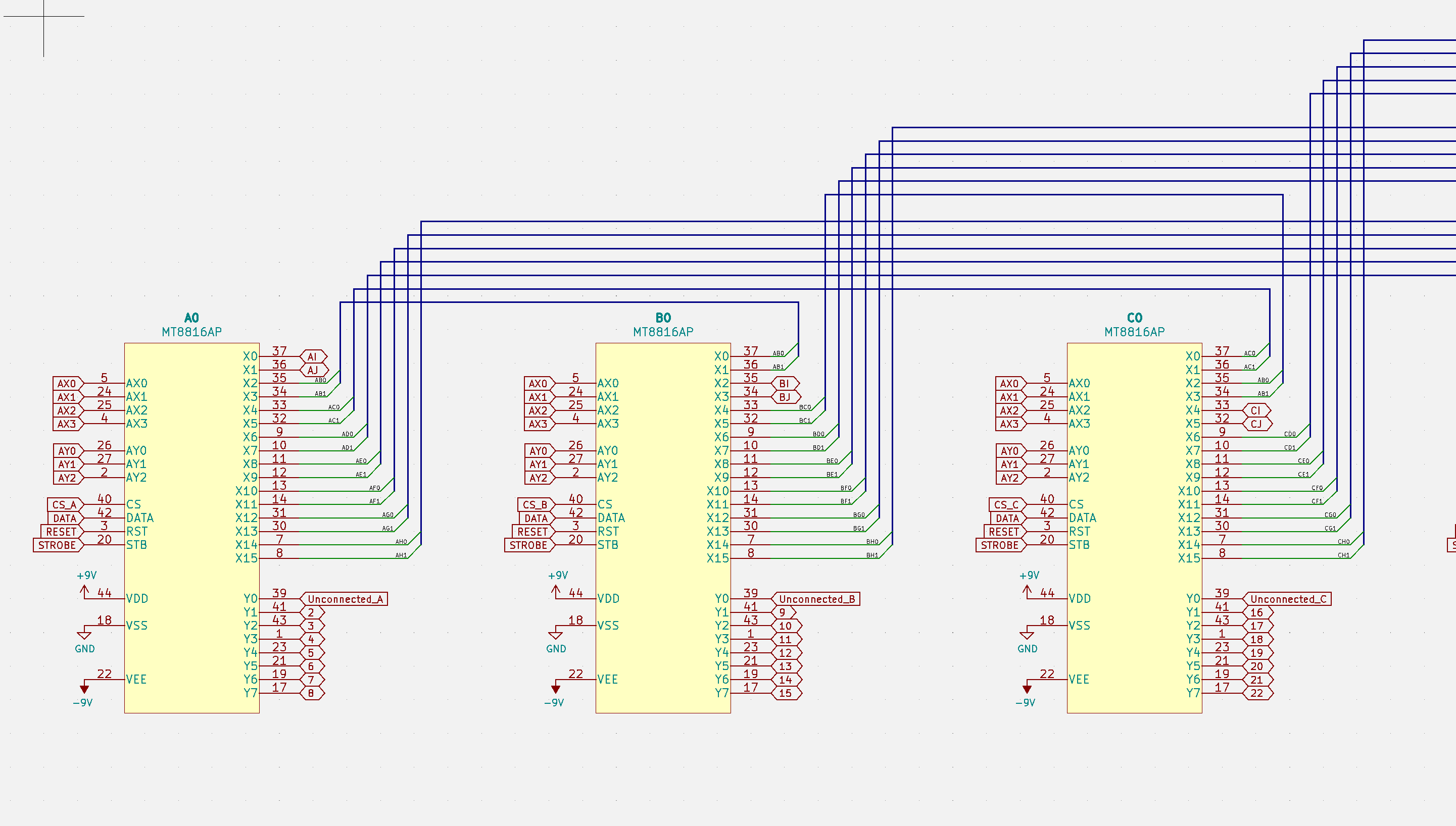
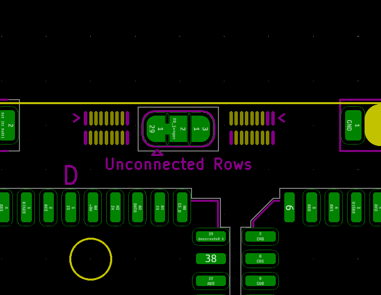
- Also every crosspoint (instead of only 4 of them) has an unconnected Y input because those were ridiculously useful to cover for times where there aren't enough direct connections or whatever. That also means there are 4 points on the breadboard that aren't connected to anything (which will probably be useful for sensitive/high voltage stuff) and their location is selectable with a solder jumper (corners or right side)
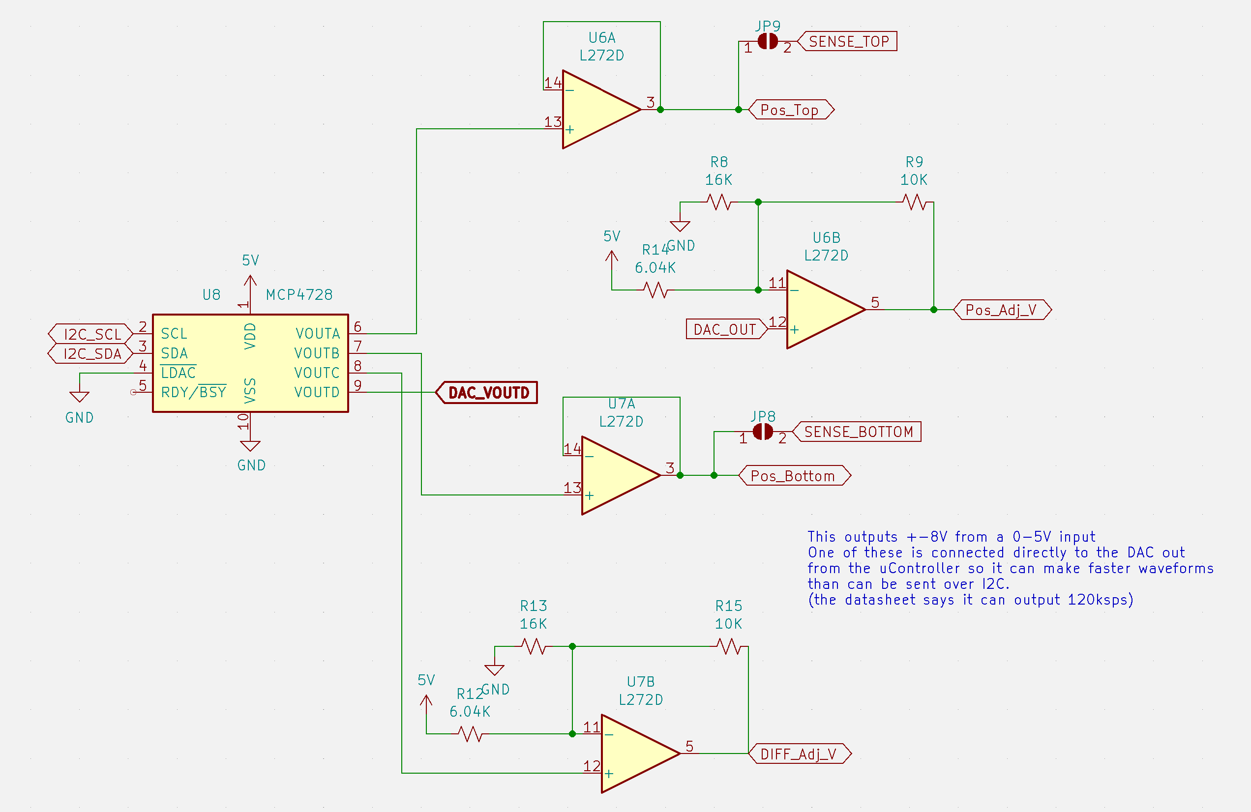
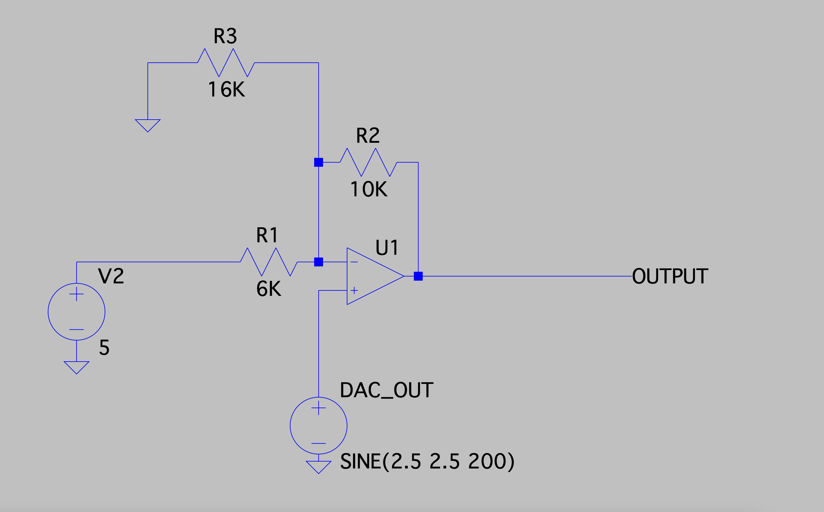
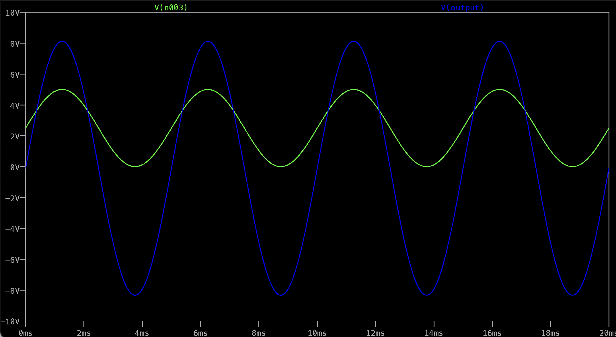
- I redid the power supplies a bit to get +-8V from the 0-5V DAC. And I also connected one of those directly to the AVR128DB64's built in DAC so I can use it as a function generator. The datasheet says it can output at 120Ksps, so if everything works basically like it does in LTSpice, it shouldn't be that bad of an arbitrary waveform generator for this purpose. (But if there's some analog ninja out there reading this, please let me know if this is going to blow up if my face.)
- The negative rails are directly connected to ground by default now because as I learned from the last version, switching grounds around with a ~65Ohm resistor in series sucks. And creating a "ground" by having a power opamp output 0V was a bad idea if you don't want it floating all over the place. But that can be changed to and adjustable voltage with yet another solder jumper. I went absolutely jumper crazy to avoid making any hard decisions.
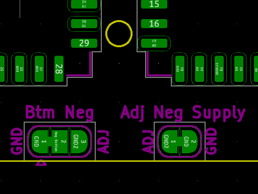
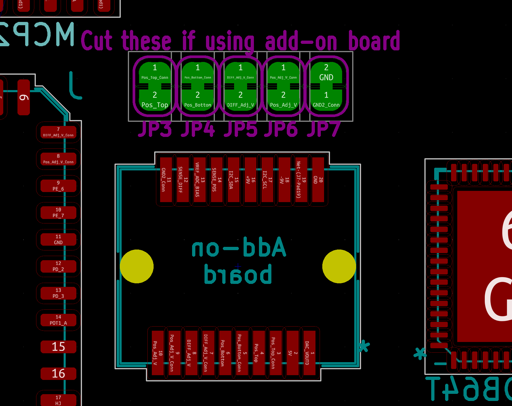
- Speaking of not making any decisions, I put an entire 20 pin card edge connector on the control board so if we ever decide to add current measurement (or anything else) we can populate it and throw in a little PCB to do that.
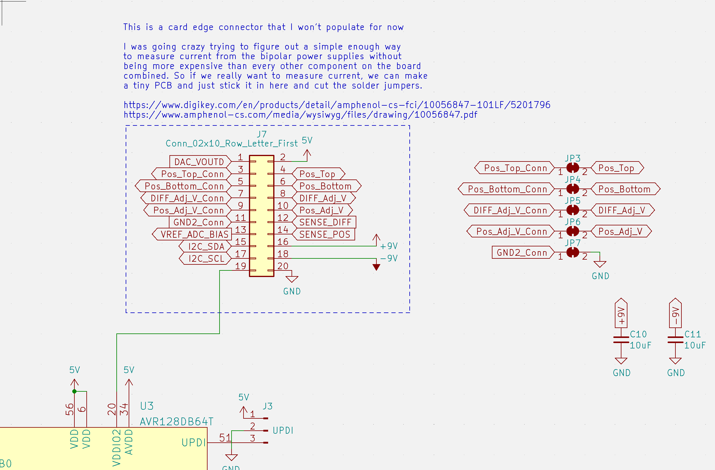
I spent about a week trying to figure out a way to measure current from the power supplies that was simple and cheap enough to be worthwhile. There's definitely some way to do this without adding a ton of parts or one really expensive chip, but I figured I'd leave that up to future us to deal with and just route every signal we might need to a connector.
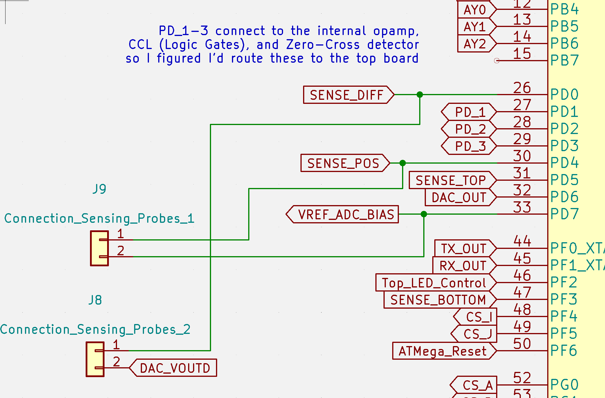
- I also added 4 probe outputs so you can just plug in a few jumpers and make connections by poking 2 points like I originally wanted to do for version 2. Probe 1 connects to the inputs to one of the AVR128DB's internal op amps, so there's a bunch of other things you'll eventually be able to use these probes for.
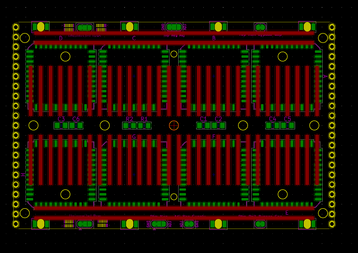
![]()
- The top board is now has holes to that line up with the holes on the back of a Jameco Valuepro breadboard so instead of painstakingly soldering the breadboard on with tiny holes drilled into the metal clamps, I can use Z Tape and to make the connections and use the screws to provide enough pressure to make that work. Or if I'm really lucky, I can use solder paste and hopefully melt it before the plastic melts too. But that seems unlikely. This is going to be a 4 layer board so I don't have to try to route around that breadboard footprint. (I'll post this KiCad footprint somewhere in case someone wants to use this approach for something else.)

Notice the clearances for those corner holes is so tight I had to rotate those chips to give me that tiny bit from the filleted corners. Hopefully I'm paying attention when I put these together.
I can tell already the firmware for this is going to be a nightmare, so it will probably be worthwhile to actually map out how everything's going to work together instead of just running in and writing code all willy-nilly like I usually do.
Discussions
Become a Hackaday.io Member
Create an account to leave a comment. Already have an account? Log In.