 Lukas Koch aka Ast
The setup on the breadboard works. LEDs are blinking randomly and I have an open-drain digital output of random bits. The current measurement is very sensitive to so shielding of the ion chamber and preamplifier is very important. Without it the output is just 50 Hz noise.

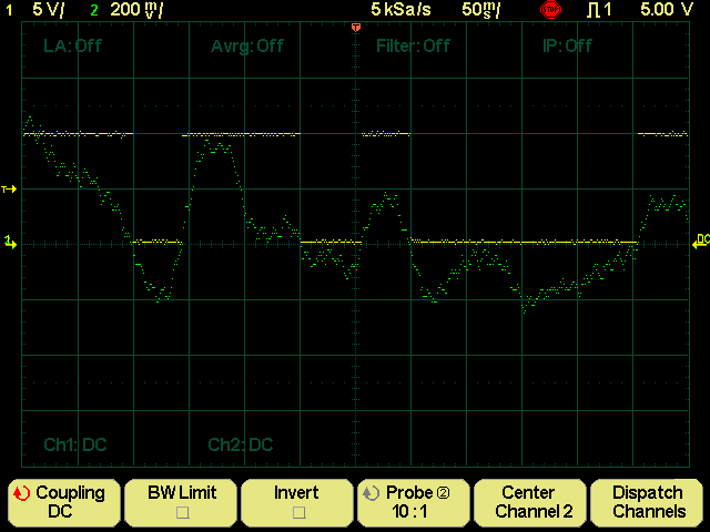
Channel 2 shows the current measurement output minus the DC offset. Since the signal is quite slow, I had to use the oscilloscope in DC mode and add my own RC high pass for reliable measurements. Channel 1 shows the digital output of the circuit. It is generated by comparing the analogue output with a reference voltage using a Schmitt trigger.
Now I need to document the working circuit and move it to a more permanent perfboard.
Discussions
Become a Hackaday.io Member
Create an account to leave a comment. Already have an account? Log In.