 Kevin Arne
First PCB Version
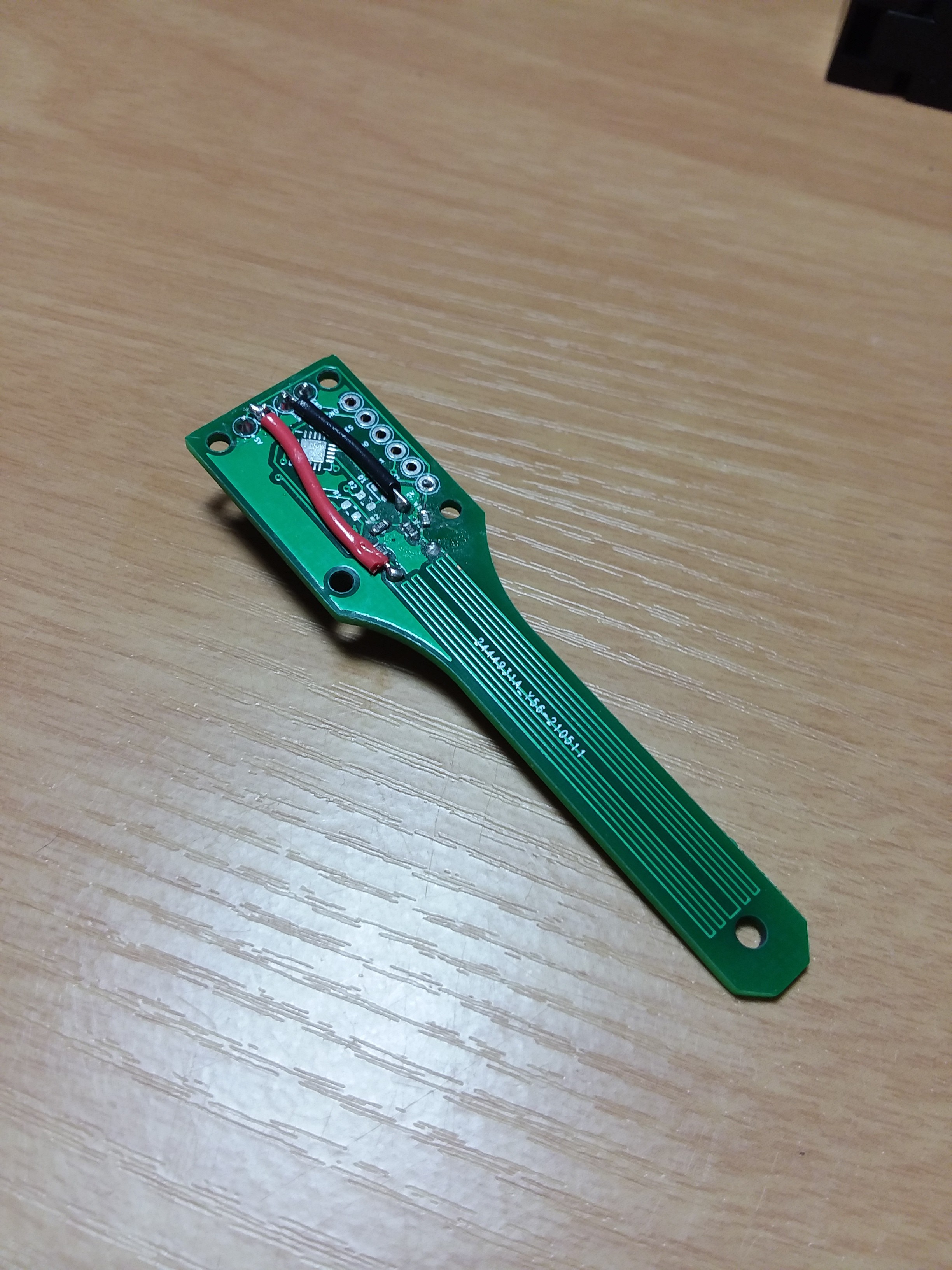
I wanted to embed a strain gauge in a PCB. I'm not sure this makes any practical sense, but thought it might be convenient to avoid the wiring and hassle of attaching a strain gauge to a load cell by embedding the strain gauge with the rest of the wiring to make this an I2C-powered sensor. Also in this version were a status LED, ATTiny85, and resistors to make a quarter bridge Wheatstone bridge.
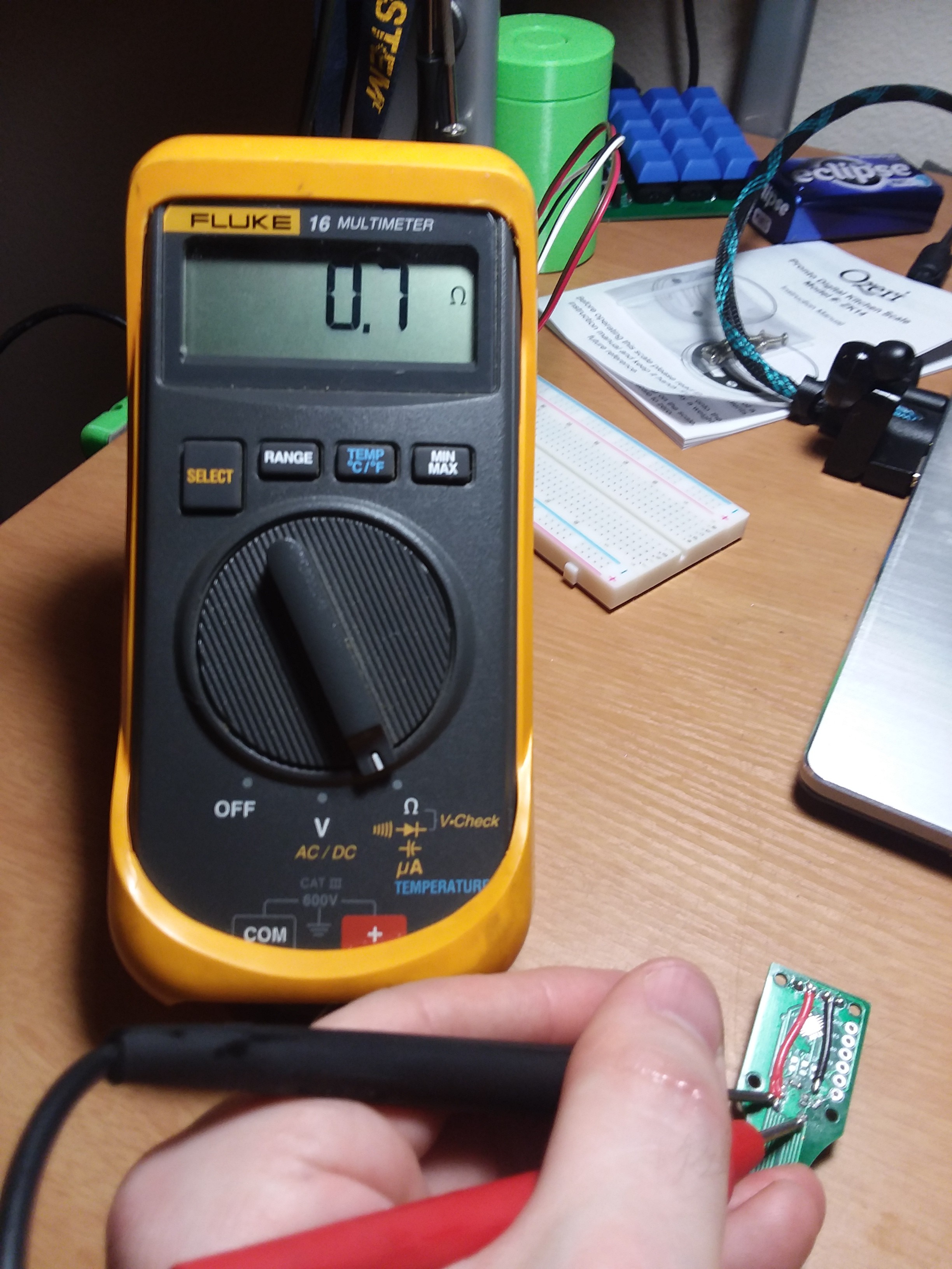
So where did things go wrong? Well I didn't even think to calculate what resistance the of the strain gauge would be. It was very low, like under 1 ohm. This was pretty problematic because it meant I needed a current-limiting resistor, which I didn't think to include. I really should've put a spot for a 0 ohm resistor just in case, but that didn't occur to me.
Even when I bodged in a current-limiting resistor I couldn't detect any change in voltage as a result of a load, because the voltage drop across the current-limiting resistor left very little resolution for the actual strain gauge. I ended up bodging in some more wires to cut the ATTiny85 out of the picture entirely to allow for easier debugging with an Arduino Nano.
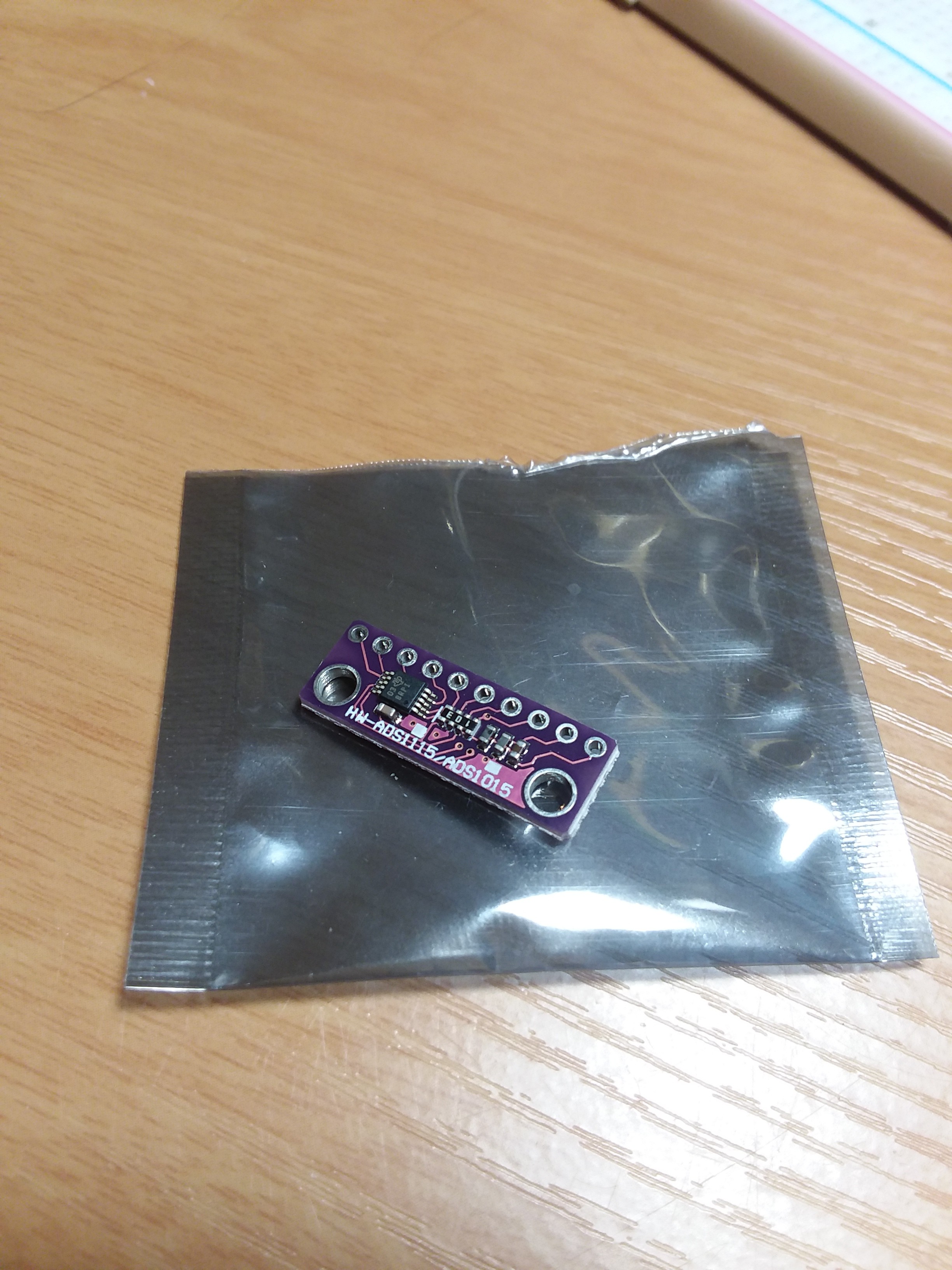
I thought this might still be salvageable (spoiler: it wasn't) if I just hooked up an ADC with better resolution. I bought a breakout board for an ADS 1015, which has 12 bits of resolution compared to the Arduino Nano's 10 bits. Still no noticeable difference when a physical load was applied.
Second PCB Version
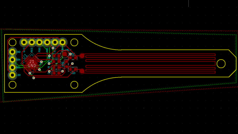
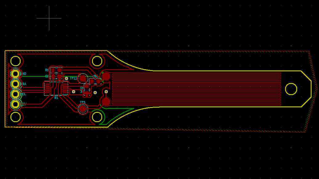
To fix the issues of the first PCB, I decided to design a new strain gauge right at the limits of my manufacturer's trace width and spacing capabilities (6 mil and 6 mil). Instead of a quarter bridge, this one would be a half bridge, which means a strain gauge on both the top and bottom surface. One would be in tension and the other in compression, creating a larger voltage difference. Instead of using an ATTiny85, I planned on an ADS 1015, even though you can't actually source them right now. I can always lift one off these breakout boards if everything else appears to be working.
Finally, with this version I could actually detect a change as a result of a physical load! The change wasn't quite as extreme as I would've liked, so I have some more tweaking to do. I'm also currently only at the stage of detecting voltage changes, not translating those into strain or weight yet.
What's Next?
Try to actually calculate strain and weight from the data I'm currently getting and compare those to known weights.
Investigate commercial scales and see if I can set something up with a commercial load cell for comparison.
Discussions
Become a Hackaday.io Member
Create an account to leave a comment. Already have an account? Log In.