 Dave's Dev Lab
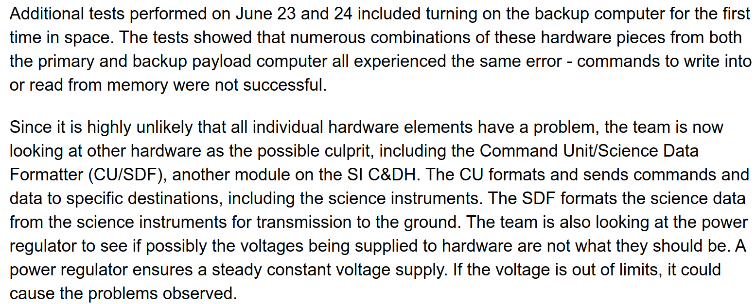
NASA has provided some updates to the debug process:
The next steps in the debug process appear to be looking at the Power Control Unit(PCU). The basic information we have about the PCU is:
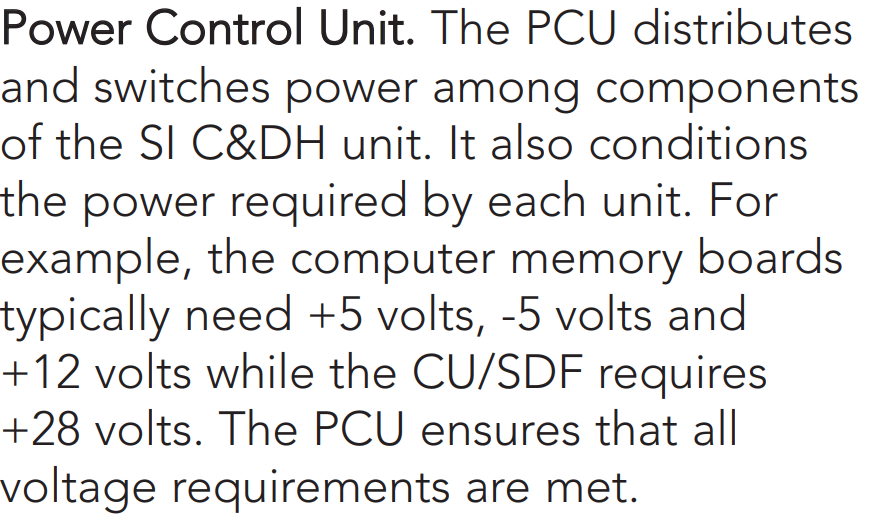
These voltages are pretty common for computing designs even today, with the exception of the +28 volts. A common ATX power supply provides +5V, -5V, +12V and -12V ( in addition to +3.3V). The PCU is marked in this diagram as A300:
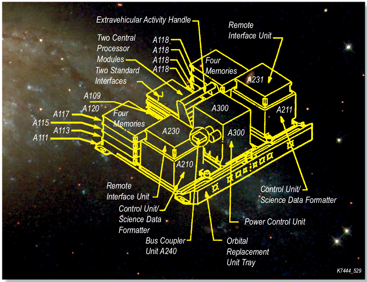
You will notice from the diagram everything seems to be duplicated for redundancy, and several media articles indicate that the PCU has a backup, however none is listed in the diagram or other NASA documentation that I have found.
Discussions
Become a Hackaday.io Member
Create an account to leave a comment. Already have an account? Log In.