 deʃhipu
I tried to fix the connection between the flex PCB and the PCB, but it looks hopeless. I ended up ripping the pad off of one of the sensors. I think I need to re-think this.
At this point, the easiest way forward seems to be to find the correct mezzanine connector for the Blackberry 8520 sensor — after all I even have a ready pinout for it! After some searching, it seems that something called DF30FB-20DS-0.4V should fit. I have ordered it, and we will see.
In the mean time, I can prepare the footprint for it. The datasheet gives me a recommended pattern:
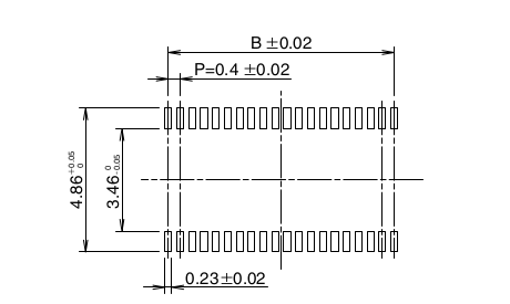
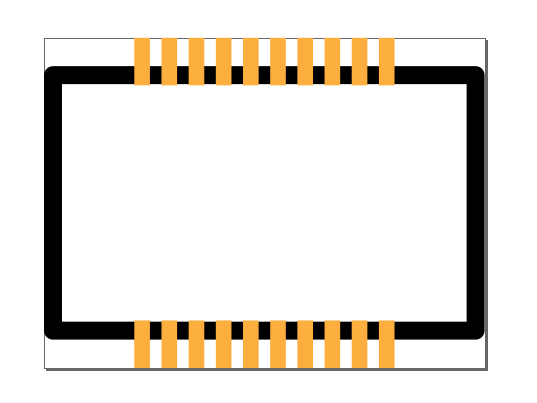
Replicating this in Inkscape just takes a few moments:
Now I just need to quickly design a PCB, and hopefully the connector and the PCB will both arrive at about the same time.
Discussions
Become a Hackaday.io Member
Create an account to leave a comment. Already have an account? Log In.