 deʃhipu
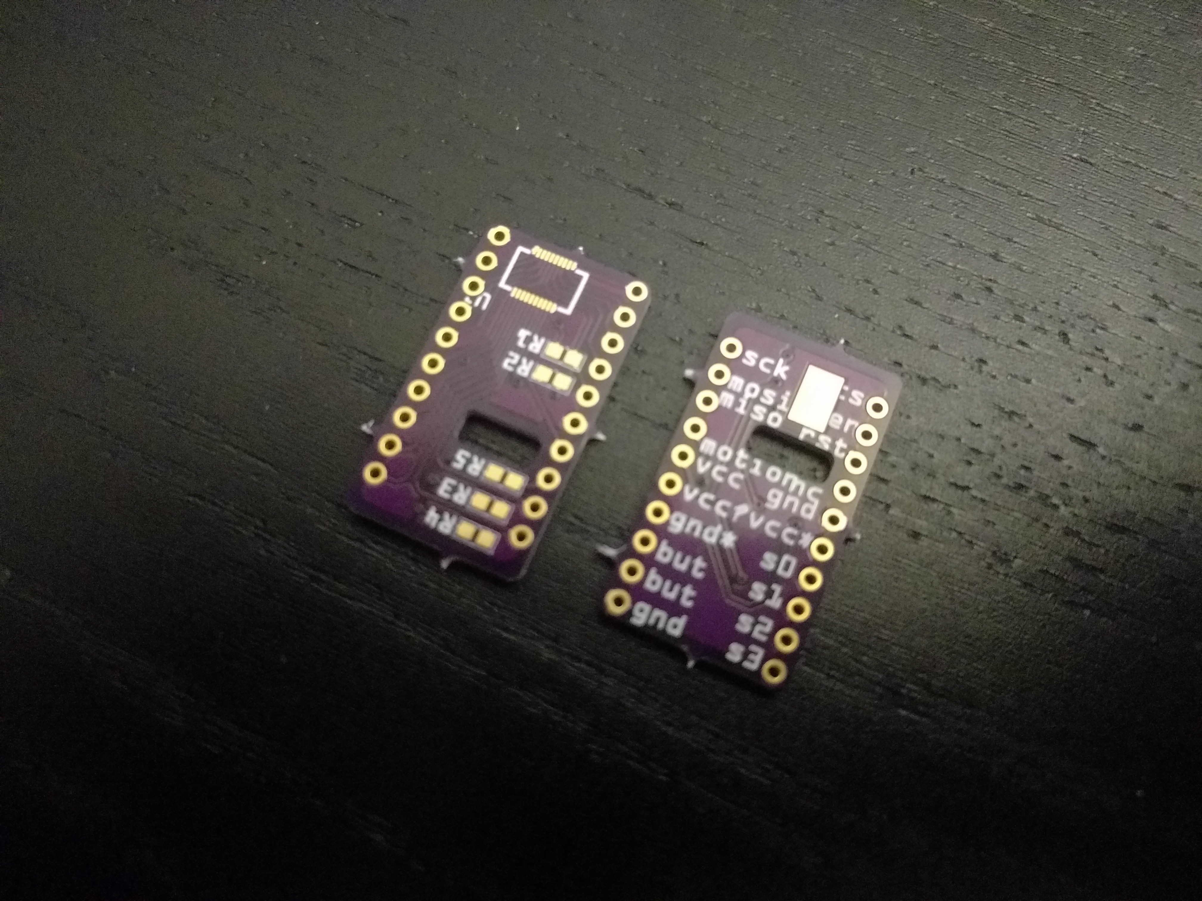
The PCB breakout for the 8350 sensor arrived from @oshpark and as always it looks great:
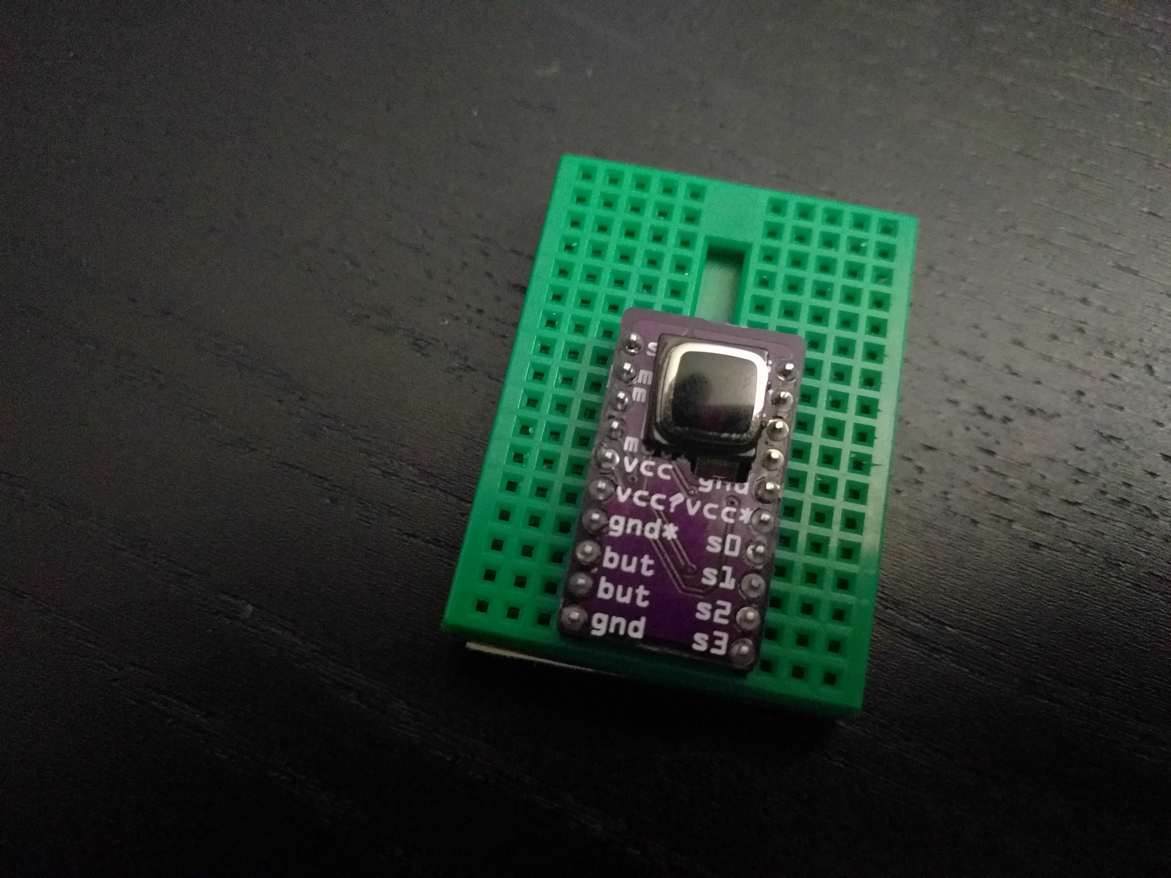
Unfortunately I miscalculated the distance between the socket and the slot, not taking into consideration the thickness of the PCB, so I had to use a file to make the slot a bit bigger:

That is fine, because this breakout is just for experimenting — the final one will have correct dimensions and only the pins that are needed.
I have everything soldered up and prepared, but I didn't yet have time to actually try this sensor yet — hopefully I can do it tomorrow.
Discussions
Become a Hackaday.io Member
Create an account to leave a comment. Already have an account? Log In.