A project like this need a custom PCB that fit space constrains...
The first version of the PCB had all of the necessary components and functions for testing and some function that didn't work...
The first design version of limiting the rotation of the laser arm didn't work as plan and the µP got stuck in reset... The second version was better with the switches in series with the motor and diodes in series with the switches so the motor still can reverse back from the limit switches.
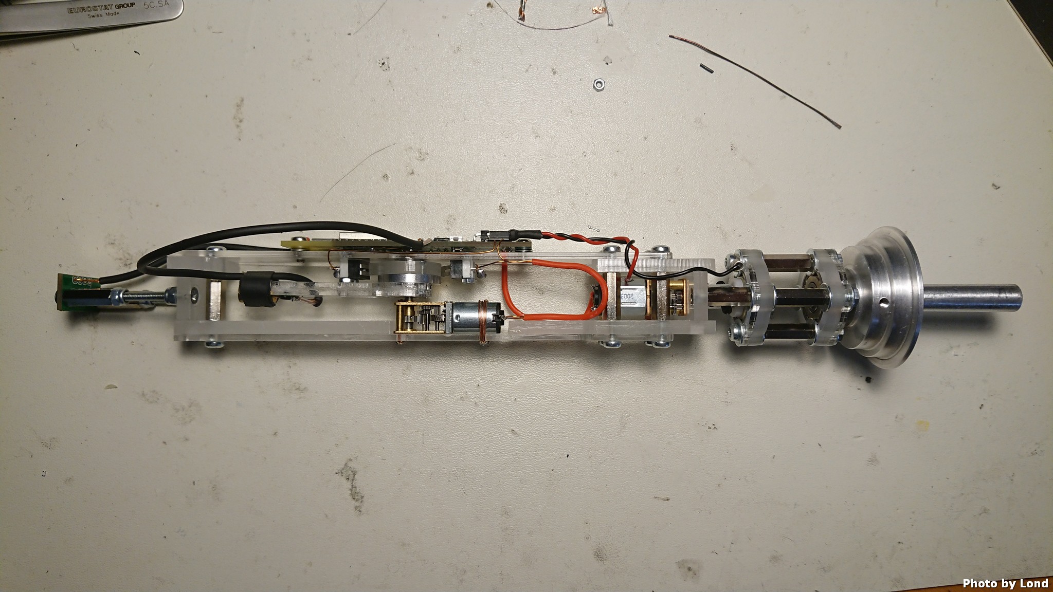
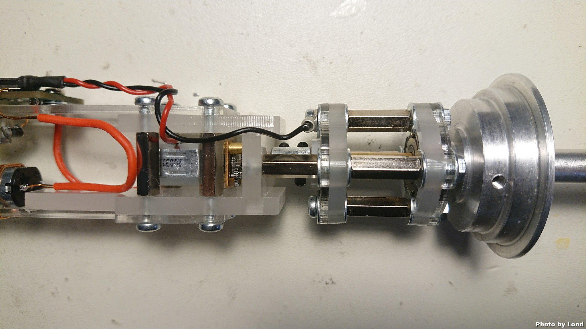
The power feed from the DC-input is routed via the motor case (positive) and through the bearings (negative).
After the bugs and design flaws was sorted out, it was time to design version 2 of the PCB.
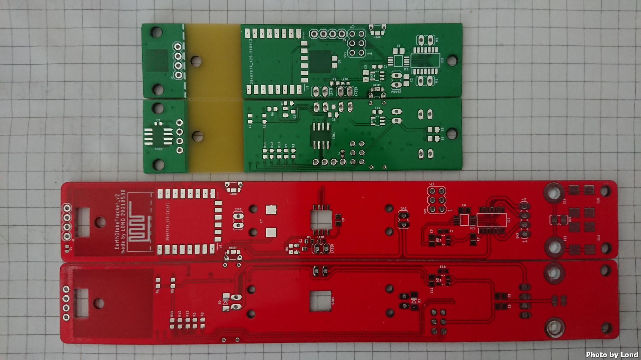
The version 2 have integrated limit switches and reverse diodes and a combined connector for both motors for easier cable management. It also have more capacitors for increased stability on the power input, not that I have noticed any problem, but when there is space then it's space for more capacitors....
One other change in version 2 is the dimension of the board, I discovered that the 2mm thick laser cut Plexiglas was to flimsy and needed reinforcing. To save space I decided to integrate the PCB as a structural part of the design.
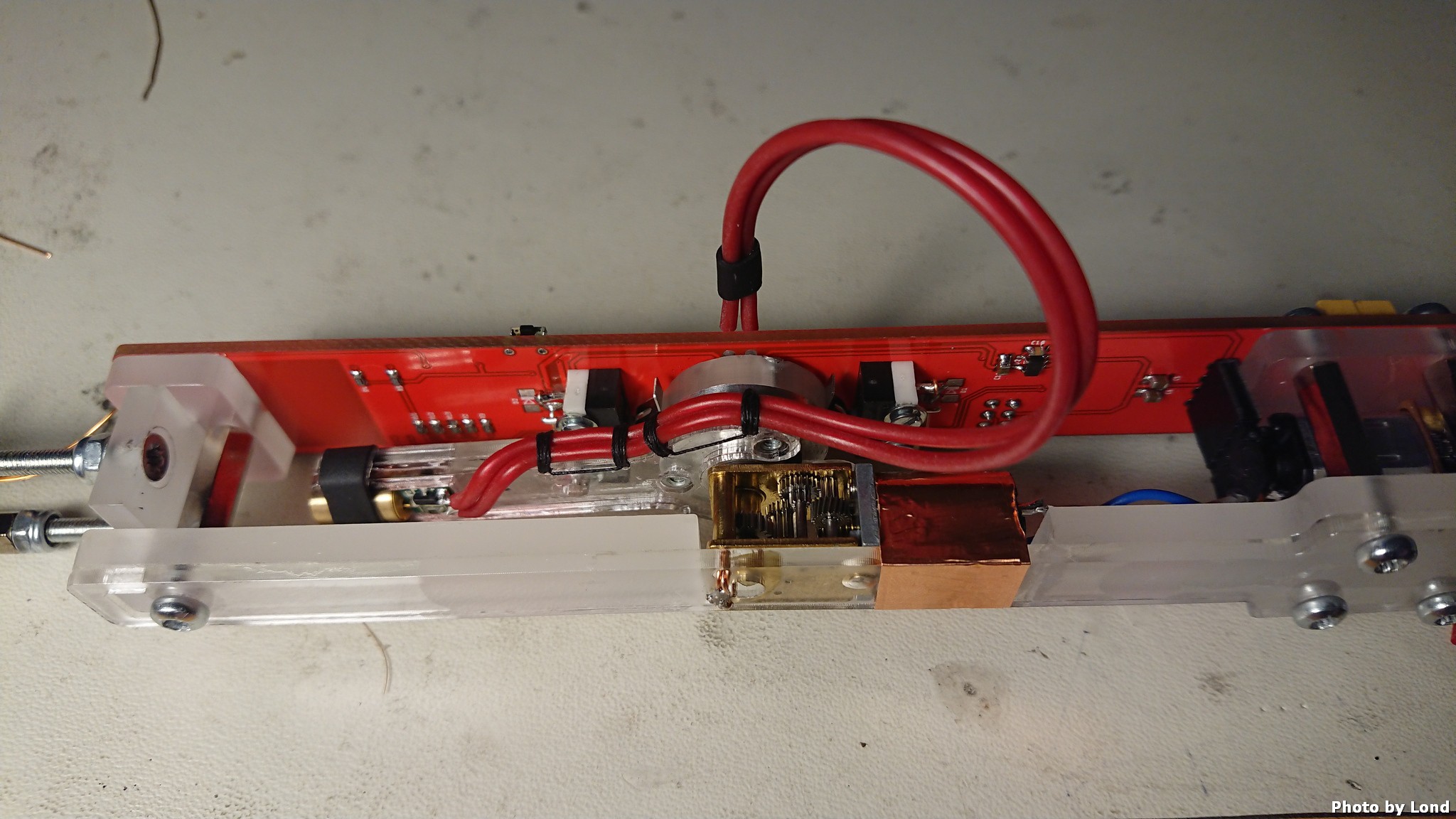
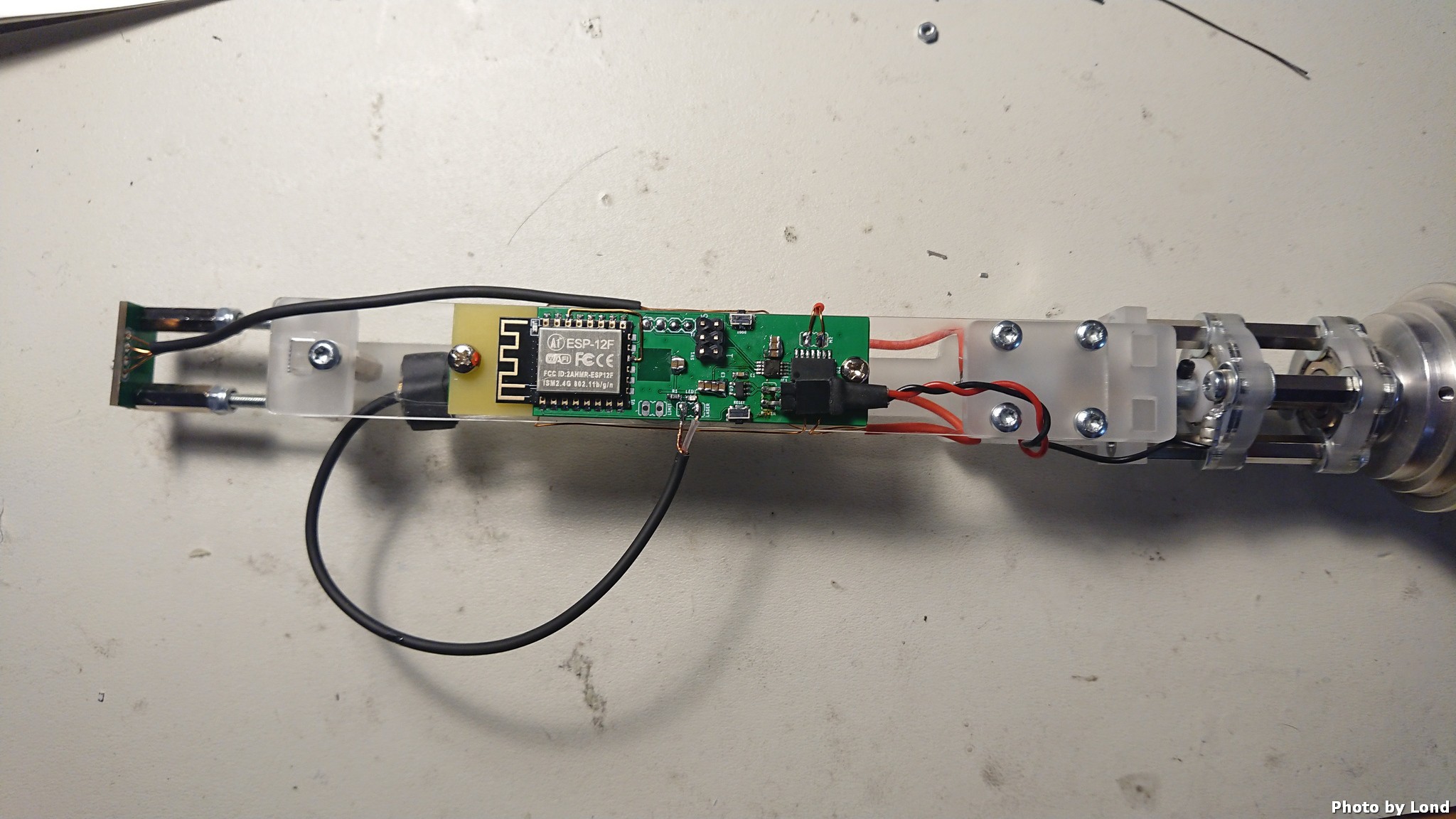
The major components on the PCB is:
- ESP-12F µP module
- 2 x AP2202-3v3 LDO:s
- PCA9633 i2c to 4 PWM outputs
- LB1836M dual full bridge low volt motor driver
- 2 x AS5600L magnetic angular sensors, i2c connected
- 2 x limit switch
- And of course resistors, capacitors, LED, a transistor and connectors
Did I mention that the version 2 PCB is RED?
Discussions
Become a Hackaday.io Member
Create an account to leave a comment. Already have an account? Log In.