To begin my design process I found some old steppers I had and designed them using Auto-desk Inventor.
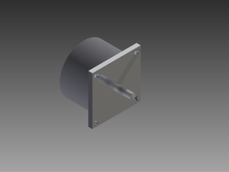
This is the motor used to turn the core
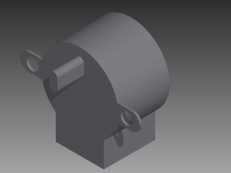
This stepper is used to turn the lead-screw, which adjusts the horizontal position of the wire
After the motors, I made the frame of the entire machine, planned out where I wanted the motors, and designed the frame.
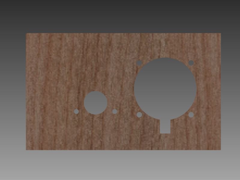
The wall of the structure where the stepper motors will mount.
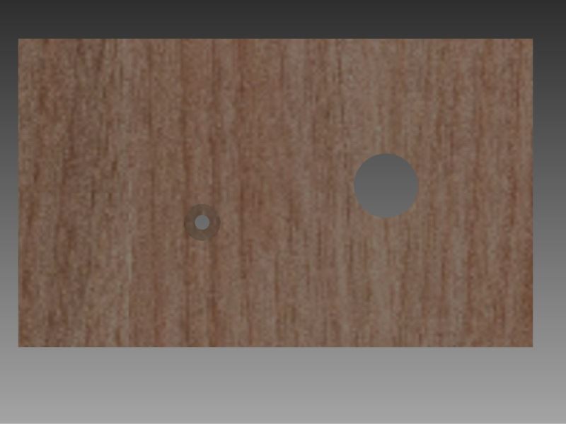
The opposite wall, where the ball bearings will go to support the shafts.
After designing the frame, I began designing the 3D printed parts there were a total of 3 parts.
The following two renders, are cut in half to allow easier viewing.
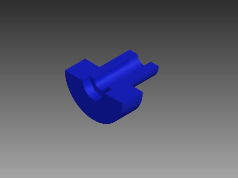
This is the piece that connects the main stepper motor to the core.
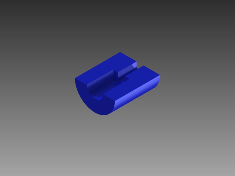
This is the part that connects the smaller stepper to the screw I will be using as a lead screw to control the horizontal position of the wire
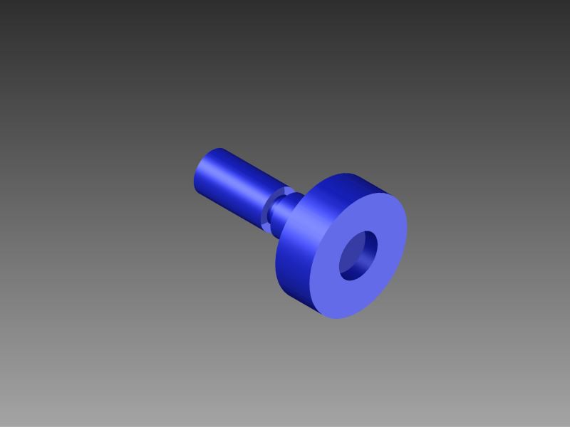
This is the piece that connects the core to the ball bearing opposite to the main motor.
 Jack Najarian
Discussions
Become a Hackaday.io Member
Create an account to leave a comment. Already have an account? Log In.