I have been using Winamp as my music player since 1998 until today, and I still think it's really cool...
I had an HP48GX calculator, and of course there was a Winamp plugin for my HP, allowing me to remote control Winamp functions from my calculator (using IR), and it's just one example...
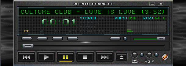
Over the years, many skins (some modern, some crazy) was made and released freely for Winamps users, one of my favorite is Quinto Black CT...
My best friend (Isaac) and I was wondering how would looks like Winamp today if the software wasn't in the limbo (cof cof Radionomy)...
Certainly it should look like modern, but keeping this retro style as modern american muscle cars does, and he (Isaac) cames with this crazy idea, about how would look not just Winamp's software, but if it will made in hardware, and just can have it in my desk but my real world desk...
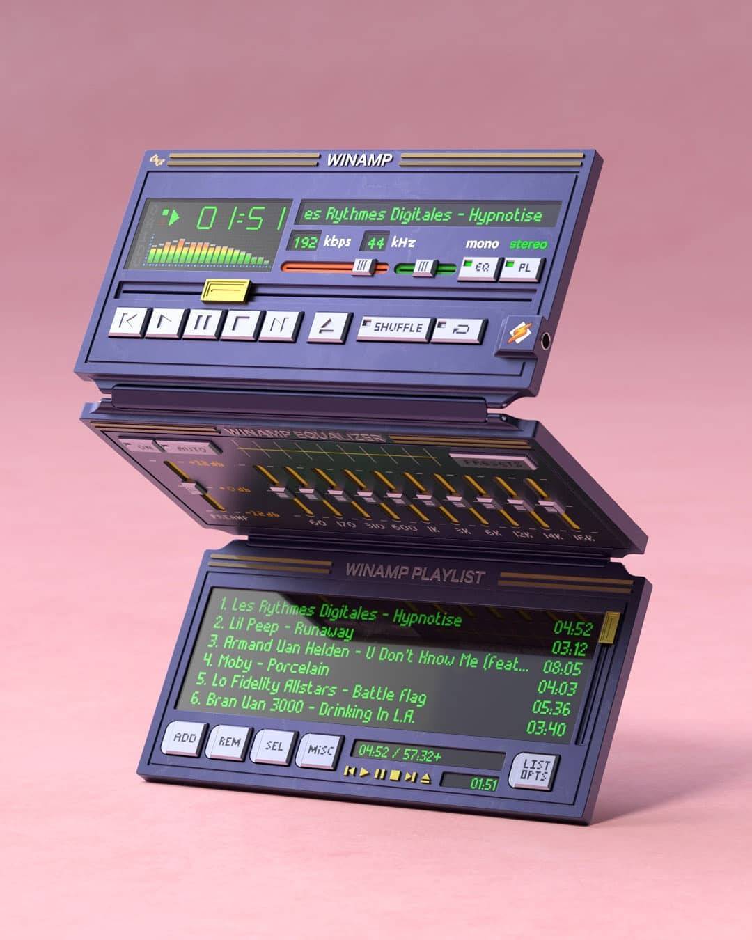
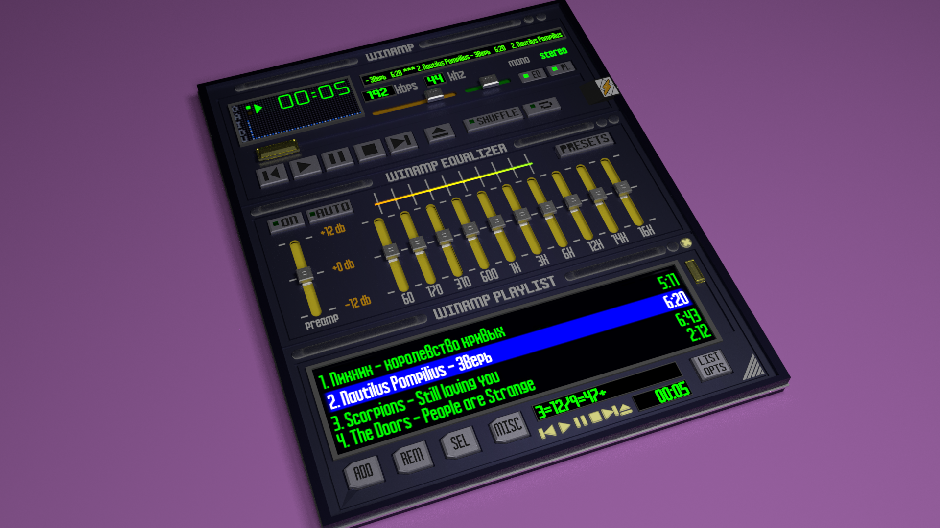
We searched the web and found many renders about how a REAL Winamp should be and look like, but none of those ideas were made for real...
Here are some examples:
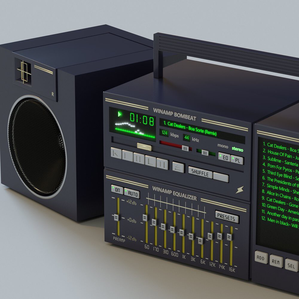
And my favorite one was this:
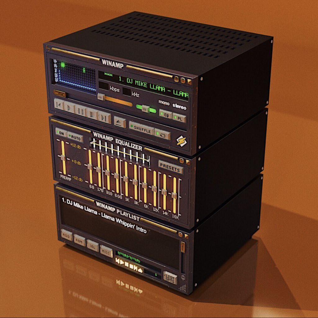
Of course, one thing is a render and another is how to practically build the whole thing...
First off all, we had to abstract which features make a Winamp to be Winamp, and what we found was this:
For the main dock:
1.- The main dock ALWAYS has 5 buttons (gray color), used to change functions, but 3 of them are quite redundant: PLAY PAUSE and STOP.
2.- There are secondary buttons, for EQ, PLAYLIST, SHUFFLE and REPEAT.
3.- It MUST HAVE and audio spectrum analyzer which is one of the coolest features about Winamp.
4.- It MUST HAVE a text bar, who shows the current music track information.
5.- The MAIN COLOR MUST BE GREEN (monochromatic): This feature had always been since the first version and brings this so RETRO feel...
6.- It MUST have a progress reproduction bar, which indicates the song time progression.
7.- All the sliders looks like 80's audio hardware sliders (but they are really difficult to implement).
In fact, I created a music audio player inspired on the Winamp's main dock some years ago (You can see here) but obviously it doesn't look like Winamp, since it lack off some of the features mentioned above...
So, I started over again, rescuing some ideas and code, but keeping in mind about creating my own real life Winamp...
First, I started from a "modern" skin, which preserves the main features of Winamp, and I choosed Quinto Black CT and blended this skin with my own skin created years ago...
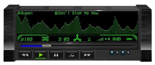
I always think about the Winamp main screen, and I believe it's so small...I understand that when Winamp was made, the software just couldn't consume many resources (my first Winamp ran on a Intel pentium mx)...
Ok then... a BIG GREEN Screen will be used, and I have this one (5.5 Inches), which I used to build this retro-game-clock before and posted here on Hackaday...
The BIG PROBLEM, but really BIG PROBLEM, are those 80's look like SLIDERS that Winamp uses everywhere (for volume, balance, EQ and so on), because doing a mechanical version of them would be expensive, bulky and noisy, but also I won't be able to remote control this kind of mechanical sliders without ataching them some sort of motor...
So... I started to play with a new ideas... more modern but clever...
I ordered long time ago about 100 RGB addressable LEDS (APA102) in small package (SMD) and I wondered if they could be used to "SIMULATE" position and movement, and also take advantage of they ARE RGB LEDS!!!
I made a PCB for the progress bar using 25 RGB LEDS, which covers about 5.5 inches along just for testing purposes...

The APA102 are Addressable and chainable LEDS that uses CLOCK and DATA serial pins, so designing with them is very easy...
Then I enclosed the bar inside a polystyrene home made box...

I didn't like the first results, because you can SEE how many RGB LEDS are inside...

The trick was to add more SPACE between the RGB LEDS and the white sheet covering the bar!
As you can see now, there is no way to know how many LEDS are inside, and the colors fuzes in such aesthetic way...


Using this technique, the PROGRESS BAR can be used to show the song progress and of course, this kind of bar will be used by the EQUALIZER later!!! =O)
Once the slider's BIG PROBLEM was solved, we focused in the designing of the main dock...
This is our concept about how a modern Winamp's skin should look like:
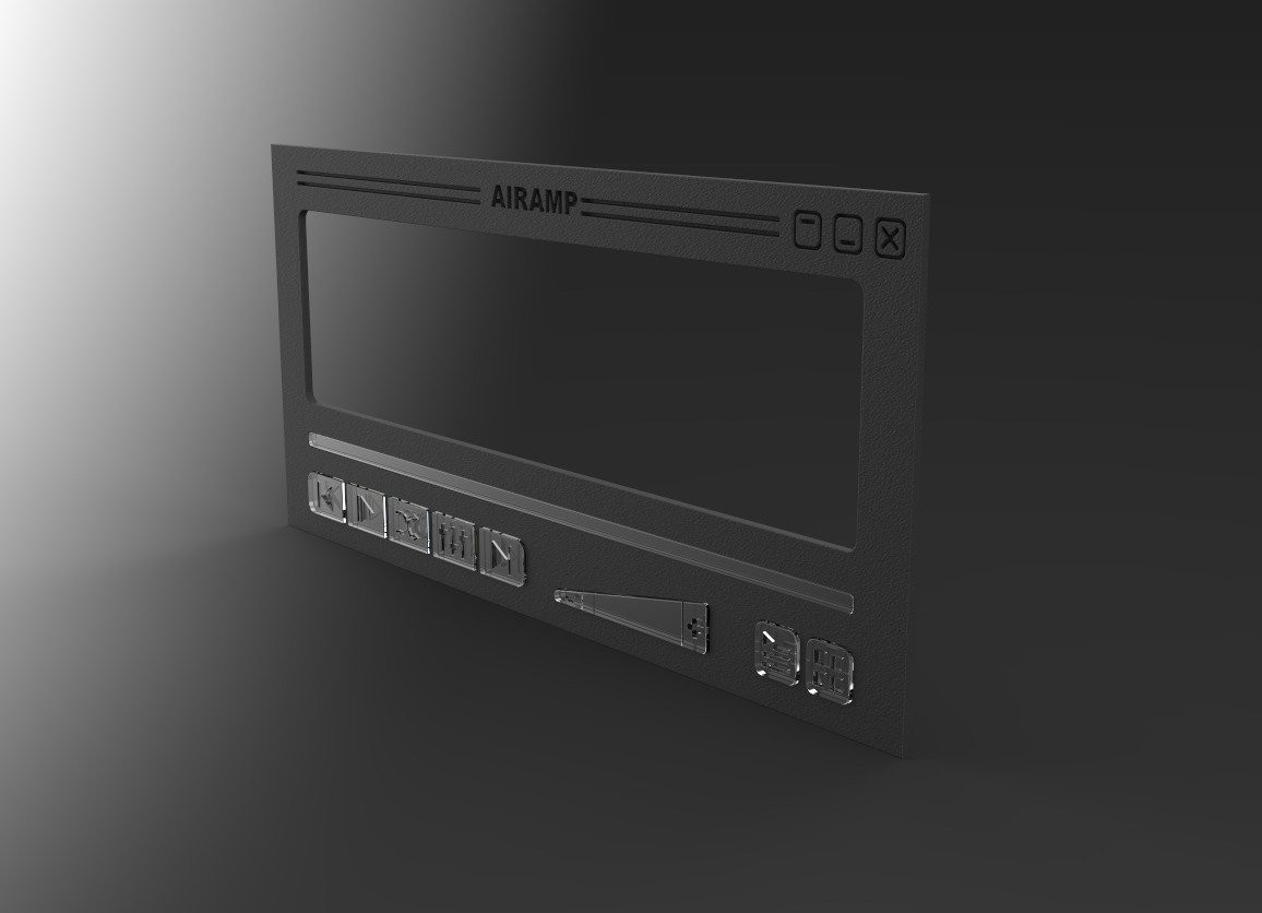
The main dock now has a big space for the screen, preserving the original 5 buttons and the progress bar.
For the volume slider, I chose a triangle form, that remains what side decreases volume, and what side increases volume...
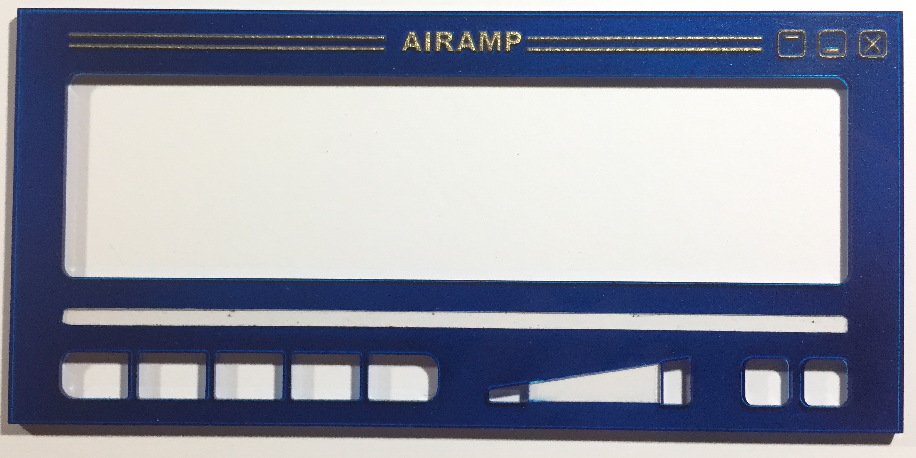
The front panel was made from acrylic and cutted with LASER, one thing I really love about acrylic, is that you can paint it the rear side and the front side will look great. Also, the bars, name and upper icons was engraved with the LASER too.
Black rear color:
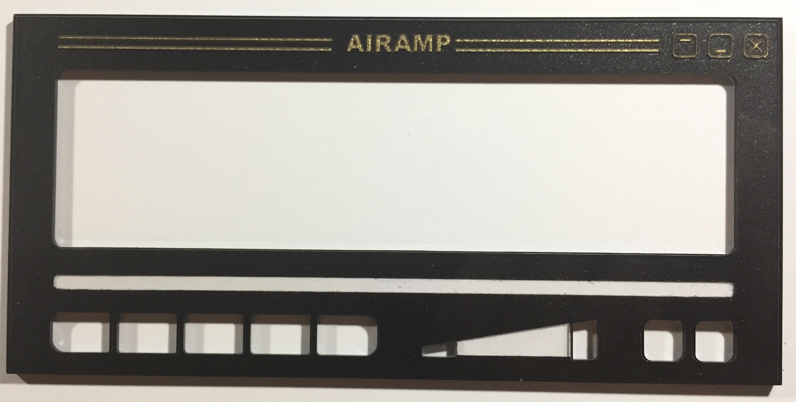
Blue rear color:
Making the buttons was very easy, I just painted first the acrylic with silver paint, and then, engrave the icons with LASER...
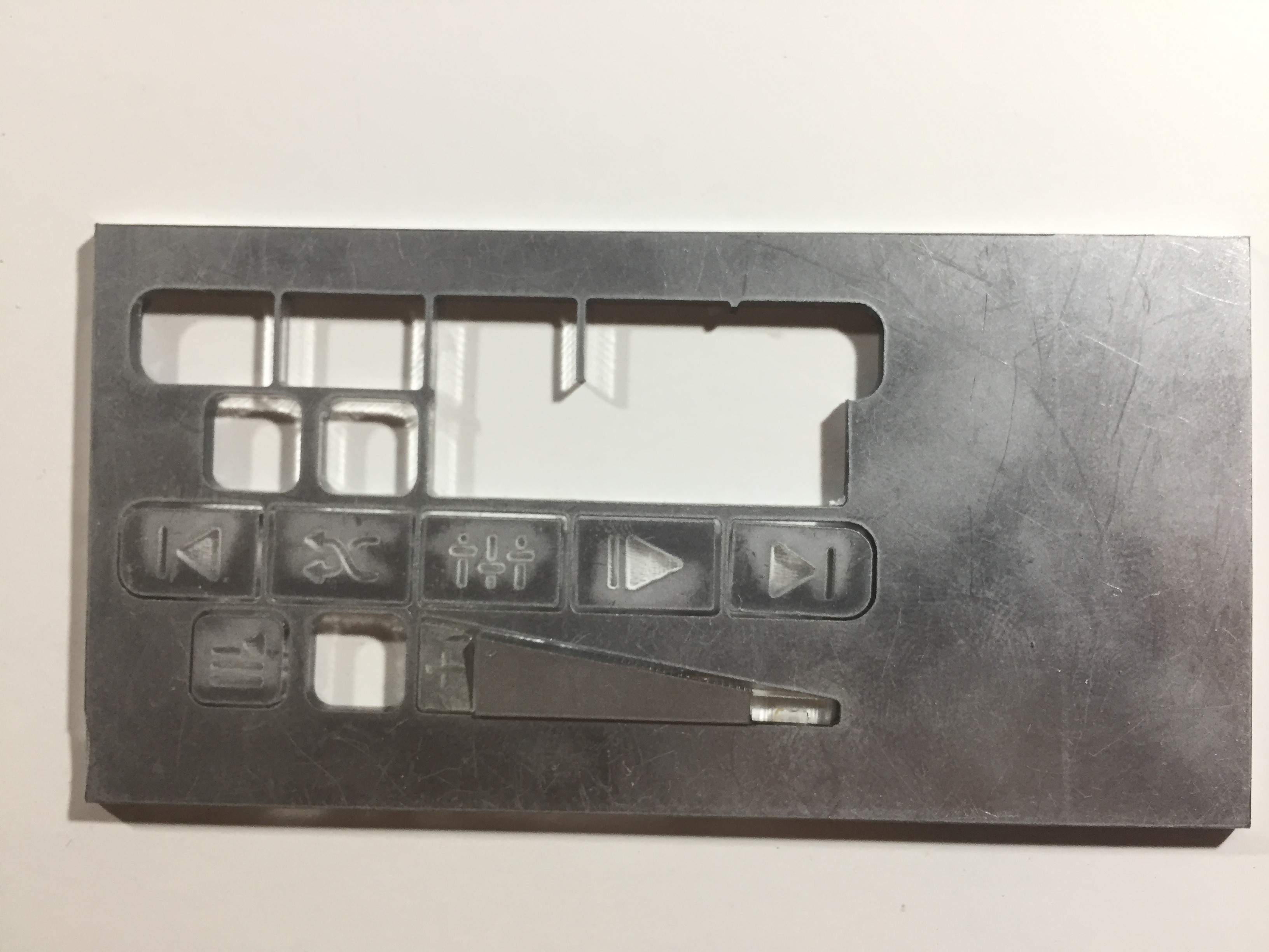
This is how the buttons looks like over the main panel:
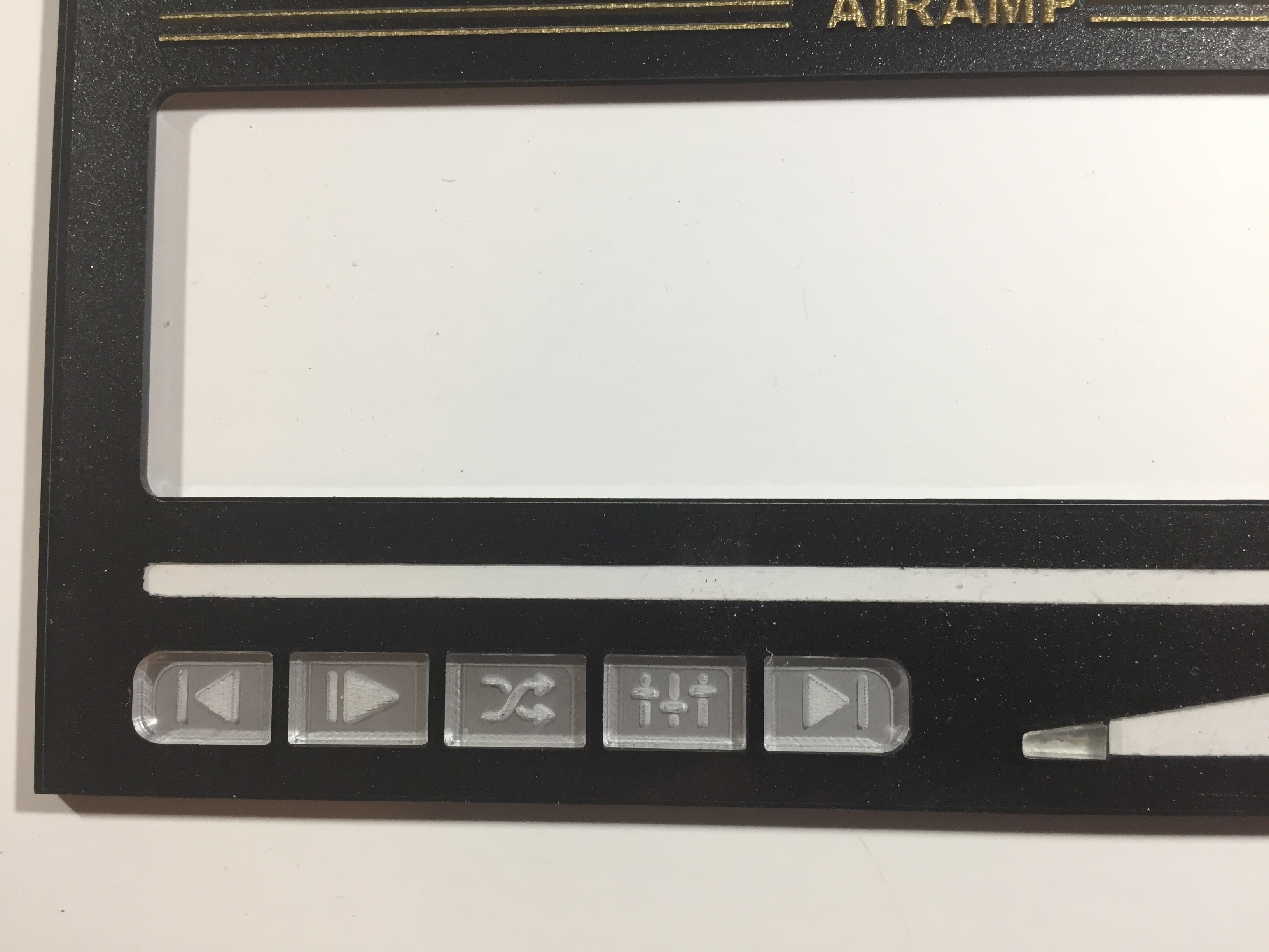
Remember when I mentioned that 3 of the buttons were quite redundant?
I got rid of PAUSE and STOP buttons, because you can do the same action using just ONE button.
Instead, I attached the SHUFFLE button and the EQ button in order to keep a minimalist design, and not overfill the main dock with many buttons...
Now, lets talk about the electronics INSIDE...
I have been designing audio players since 10 years from now, so, there is not a fast way nor Do It Yourself in one day an audio media player, but I will explain as many details as I can, about hardware and firmware...
This is the MAIN board I used to build this prototype:

It was designed based on a microcomputer design, which means, that the microcontroller acts as microprocessor, and have the characteristics of a minimum system:
* The "CPU" is based on PIC18F87K22 microcontroller, used as microprocessor running at 64 Mhz
- The internal RAM on the PIC is used as "cache" memory...
* The system has external 512 KB static RAM for data and program storage
* The system uses a uSD card, as HDD drive, it can access up to 512GB cards and uses FAT32 file system
* The system uses VLSI VS1063 chip as "sound card". The VS1063 can decode FLAC, MP3, WMA, WAV, OGG and ACC audio files formats.
* The CPU can manage different screen types, in this case, an OLED screen
* Also the CPU has a built in keyboard manager firmware
* The system can drive easily BlueTooth or other wireless audio system through I2S
*The system has several general purpose I/O pins, analog and digital.
The idea behind this kind of system, was to program an OPERATING SYSTEM inside the microcontroller FLASH memory, instead of write direct code in it, allowing to run different apps or external codes...
All the OS firmware was coded in assembly language and has these capabilities:
* It has it's own language program, wich works in a similar way as Python, that means, it's a dynamically typed coded language!
* It has a code parser, which allows to differentiate between multiple program language, such as HTML, HTTP and it's own code
* The OS can manage DOS commands, in order to control all the file system structure build inside
* Supports FAT32 file system
* Supports LFN (Long File Name) entries
* Supports 32 level path directories entries
* The parser allows to have a coded web server inside
* Supports reading files, creating files and writing files
Talking about audio files, the OS can extract metadata TAGS:
* Supports ID3V2 MP3 tags, in all versions
* Supports OGG Vorbis tags for OGG and FLAC audio files
* Supports M4A Atoms TAGS
* The operating system has digital signal processing libraries, such as FFT, RMS calculations and so on...
This is the OLED screen, it has a size of 5.5 (diagonally) and a 256 x 64 pixel resolution, in 16 gray levels
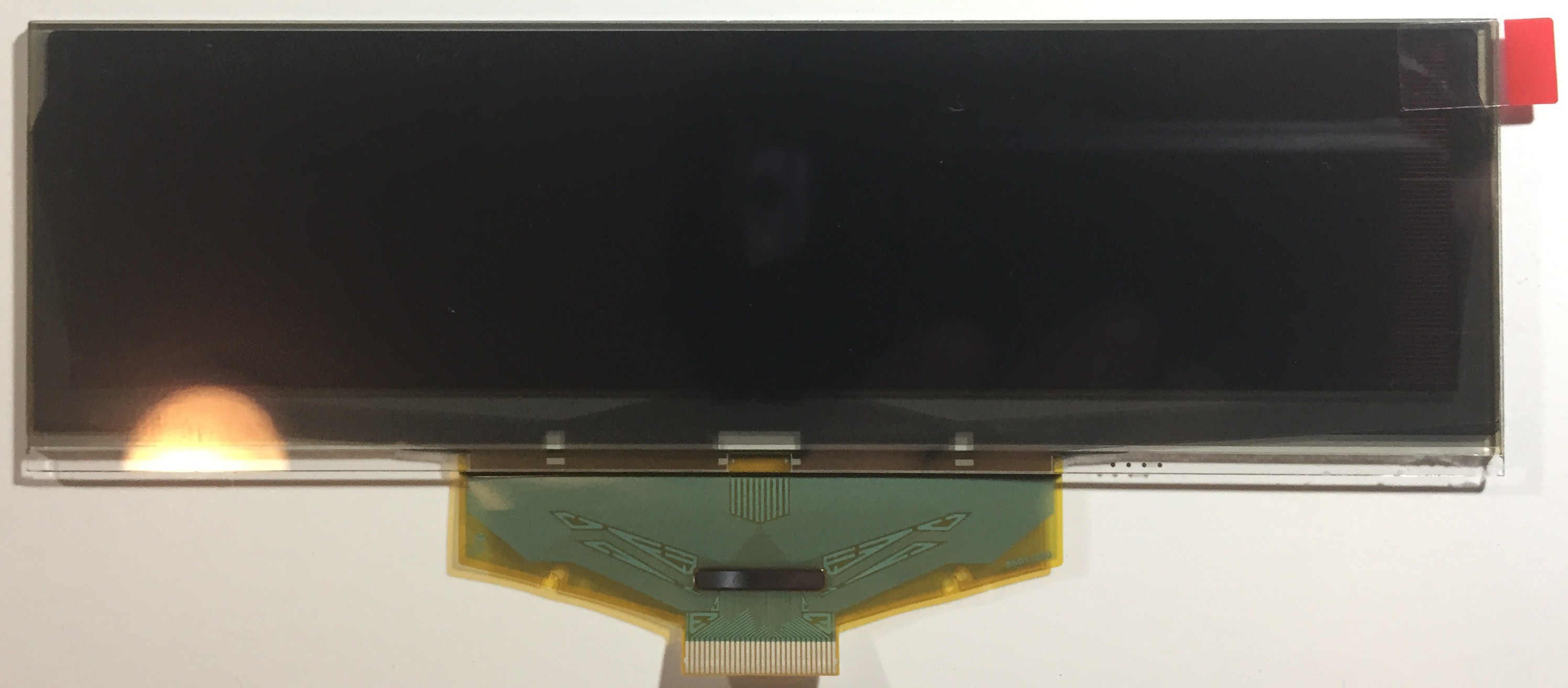
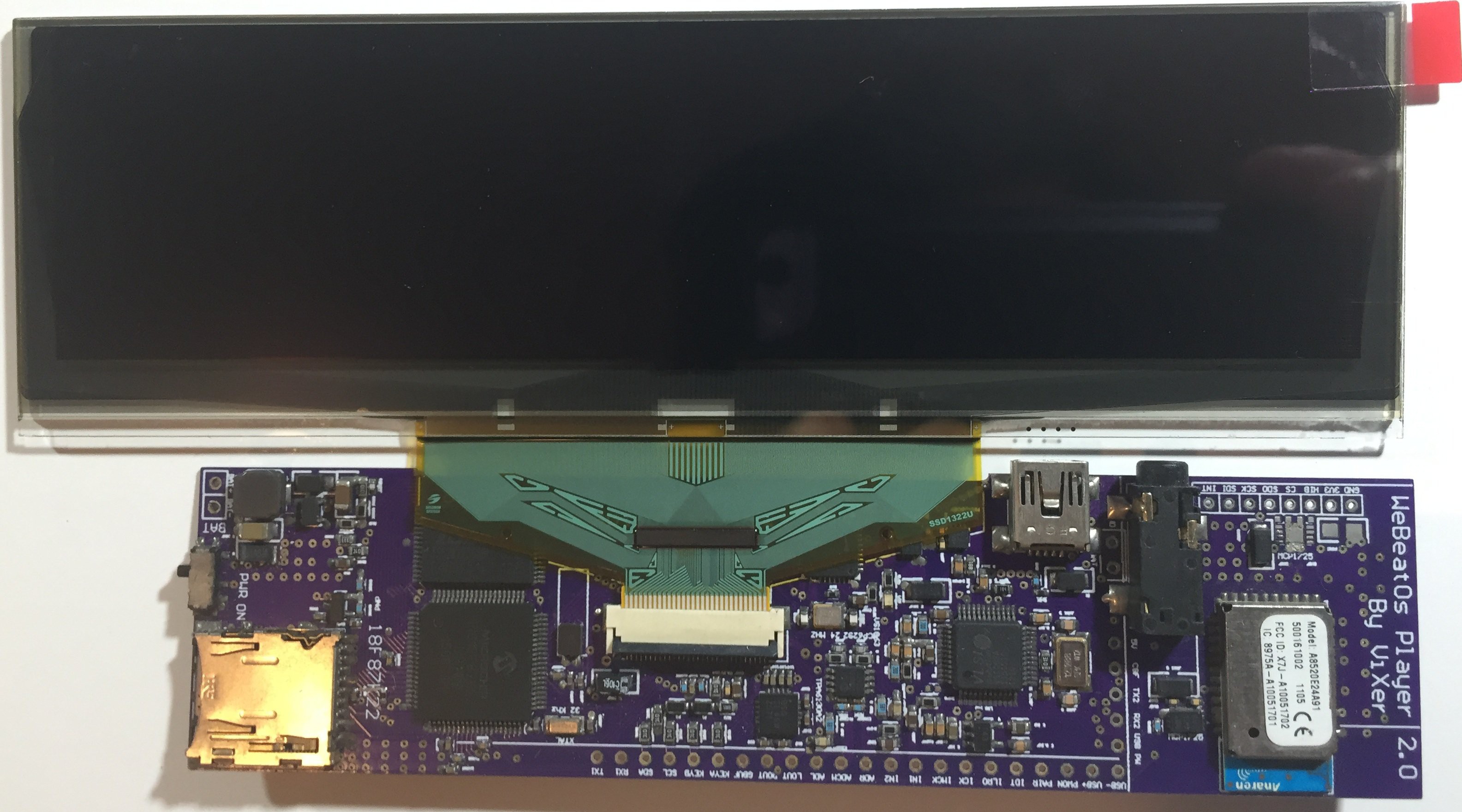
I think this OLED SCREEN is PERFECT for the project because it complies with the following criteria:
a) It's BIG, you can see it anywhere inside a room
b) OLED has a superior CONTRAST against LCD
c) The color is GREEN, wich is mandatory in Winamp
d) This screens feels so retro and nostalgic, like those old phosphor CRT
Does anyone remember (this GREEN) Prince of persia when it was released for Apple II?
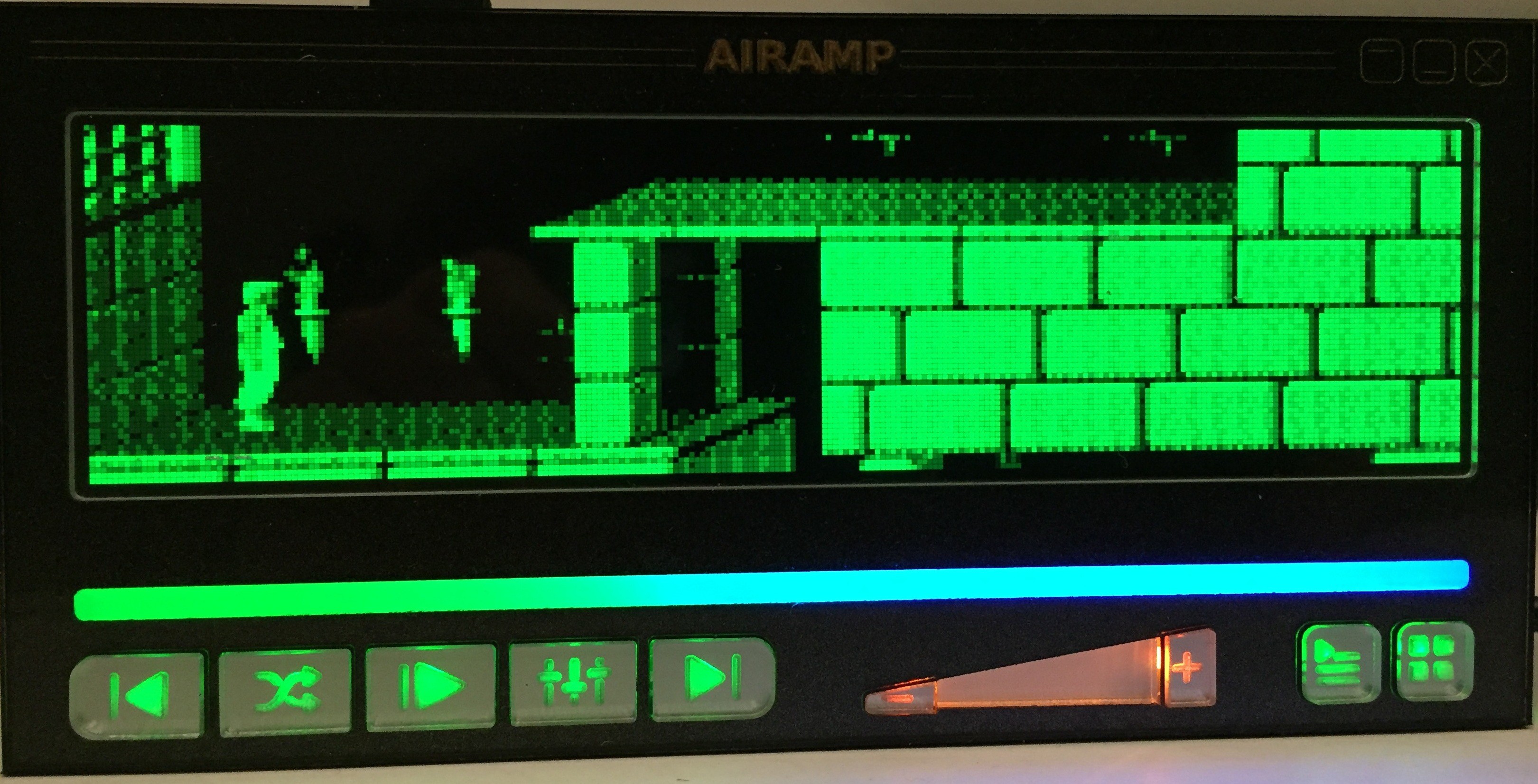
Designing the music player app:
When you watch the audio player app, it's easy to took for granted all the elements that you are seeing, but you never think about how hard and how much time took to design it....

Let's start explaining all the items...
The music player app SKIN was made in Pixel Former, which is a great software to do PIXEL ART...
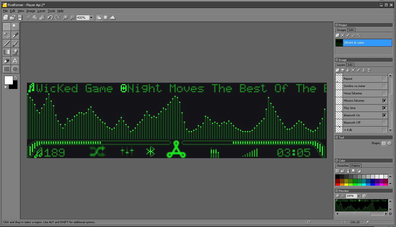
This software allows to get a clear idea about how all elements will look like once they are coded and running into the player app...
1st ITEM: FFT

The audio spectrum analyzer uses 256 x 40 pixels of the OLED screen.
When AIRAMP is playing audio, the following actions take place:
1.- The PIC reads the audio file from uSD card, and creates a memory buffer who will storage about 30 ms of audio data: The exact amount of memory depends which audio format is used (mp3, flac, aac)
2.- The PICS sends it's audio data to the VS1063 decoder, who will decode and reproduce the music
3.- In the meanwhile the PIC reads about 256 audio samples from 2 ADC inputs, one input is used for LEFT channel and the other input for the RIGHT channel, each channel is sampled at 80 Khz. So basically each audio channel is sampled at 40 Khz, wich is 2 times the max audio frequency (Nyquist theorem).
- The sampling method uses interruptions, and the interruption has a "DMA" coded inside, so all the samples are stored automatically in the internal memory of the PIC.
The samples for the FFT, are the sum of the Left and the Right samples, in order to have a MONO audio channel that represents all the audio data...
The FFT runs at REAL TIME (thanks to assembly language): As the FFT works, another batch of 256 audio samples are being acquired via interruptions.
This process creates a PIPELINE divided in 2 process:
While the audio samples are captured by interruption, a FFT is working with the last samples batch,
By doing this, all the audio information are captured without losses, and in fact, provides REAL time audio capturing....
In fact, in the time period between 31 ms, which is also the period for screen refresh, the PIC can do SEVERAL FFT, not just one, and the PIC calculates the PEAK values of all FFTs. The FFT peaks, are the ones that will be displayed...
The audio spectrum analyzer behavior, is like a Vu-Meter, because the audio PEAKS rises immediately and then the peaks decays slowly, simulating the charge and discharge of a capacitor.
-The FFT doesn't require a high resolution from the ADC (16 bits), because the audio spectrum area only has 40 vertical pixels to represent the data, so, the 12 bit of the PIC18F87K22 are more than enough
2nd ITEM: RMS Vu-Meter

In the reality, an analog Vu-Meter behaves like a RMS or average level audio meter. That is because an analog Vu-Meter has mechanical inertia, which prevents sudden movement in the needle.
So, when an audio peak presents, it doesn't move the needle immediately to the right corner, instead, it only moves a little if the audio peak is fast, behaving like a low pass filter or like an average meter....
In a digital Vu-Meter, there is no inertia, so an instant peak can be captured but not observed, as the human eye can't see at 20,000 frames x second....
That is why I chose show the RMS audio level instead of the peak level...
The PIC already had captured 256 audio samples from it's ADCs, so, not only the FFT uses these samples, but RMS values are calculated for each audio channel...
3rd ITEM: Song TAGS info...
This part of the code took several months...

In the beginning, there were only WAV files, and WAV files doesn't have TAGS, such as SONG NAME, ARTIST NAME o ALBUM NAME, nor nice COVER pictures...
Suddenly (1995), the Fraunhofer-Gesellschaft created MP3 audio format, but again... not audio TAGS were supported...
The only way to encode TAGS was in the Long File Name (LFN) but in those years, Microsoft LFN patent prohibited its use out of Windows ecosystem, making impossible for portable audio player or another third party to use LFN as method for TAG encoding...
Then, in 1996 Eric Kemp alias NamkraD creates a solution to this problem, adding a chuck of 128 bytes of data at the end of the MP3 file, named ID3...
Winamp supports ID3, it's and easy way to add TAGS but lacks of data space, also, is a pain in the * reading first the last 128 bytes of an MP3 audio file before playing...
The ID3 evolves into ID3V2, which has different versions, not always compatible between them...
ID3V2.4 wich uses UTF-16
AIRAMP supports all the ID3V2.X versions, but not the version ID3V1, which is obsolete...
Each version of ID3V2 added new features in a more coherent way to encode not just Music metadata, but also COVER pictures and future information.
When AIRAMP plays an MP3 file, it searches for ID3V2 version, then search for the following TAGS:
SONG NAME
ARTIST NAME
ALBUM NAME
IF the MP3 file doesn't content ID3V2 data, then AIRAMP uses the Long File Name of the archive to display the information, as LFN patent is currently expired... =O)
AIRAMP also suports UNICODE formats UTF-16 and UTF-8
AIRAMP also supports TAGS for the OGG Vorbis, FLAC (wich is contained into OGG) and AAC (M4A)
You can read about OGG Vorbis HERE
You can read about ACC (M4A) HERE and HERE and also HERE
AIRAMP practically supports all kind of tags, including those aberrations FLAC files which encodes metadata in ID3V2 format!!! (True history)
One of the coolest things about AIRAMP's music TAGS, is when all the information uses more than 256 pixels, when it happens, all the text is shifted smoothly LEFT shifted allowing 255 chars of information...
4th ITEM: Player App information

The other items showed in the OLED screen are: (From LEFT to RIGHT)
1.- Song NUMBER as founded in the uSD card
2.- Shuffle or continuous ICON
3.- Equalizer On or Off
4.- Bluetooth On or Off
5.- AIRA LOGO
6.- File Format ICON: MP3 Icon, FLAC Icon, OGG Icon, M4A Icon
7.- Volume bar
8.- Reproduction time
Programing all this stuff took about 1 year and a lot of reading but I was very pleased with the results...

Here is the result!!!
- Basicalyy, AIRAMP is a microcomputer, so, in can not only play music but do a lot of things!!!
Our philosophy was that everything in AIRAMP must be alive!!!
AIRAMP has an RTC built inside, which has not only clock, but a calendar with date and alarms, so obviously it can have a CLOCK to show time...
...But instead of programing a boring clock, we wanted to add life to the clock... We already had did it with Arkaclock, and all the points began to connect!!!-Arka Clock is not only a CLOCK but a RETRO GAME, so, why not add into AIRAMP a bunch of retro games?
- So, there will be games...
- AIRAMP has 3 ways to connect with the outside world:
1.- AIRAMP can drive directly an ESP8266 module to provide WiFi
2.- AIRAMP can drive BlueTooth (BlueGiga), so not only music can be broadcast or received, but data too
3.- AIRAMP uses a Nordic NRF24L01+ to connect with electronics hardware and we uses the NRF to program AIRAMP via bootloader...
- All this ways to connect AIRAMP with the REAL world can be used to add iOT and controls external home devices (How about changing the room color light according to the music genre?)
- AIRAMP will have some home control automation in the future!!!
So, we take some weeks thinking about how an APP menu should look like, because it must still looks retro but modern, and the result was this:

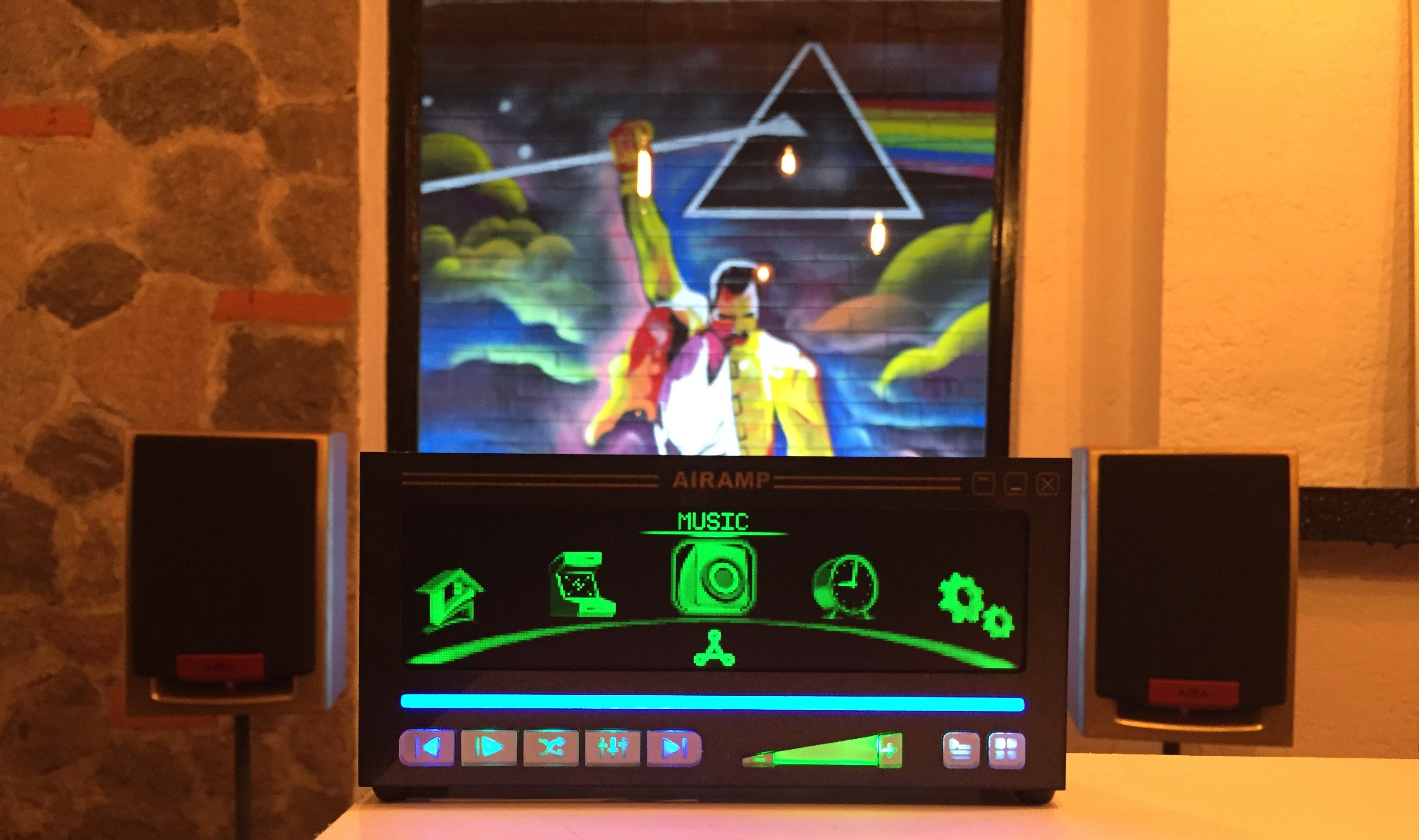
One of the coolest features that we are currently working is to connect AIRAMP to a smart phone through WiFi, making an APP who can remote control ALL the AIRAMP's functions and play music but saving storage space on the smartphone...
 Victor Serrano