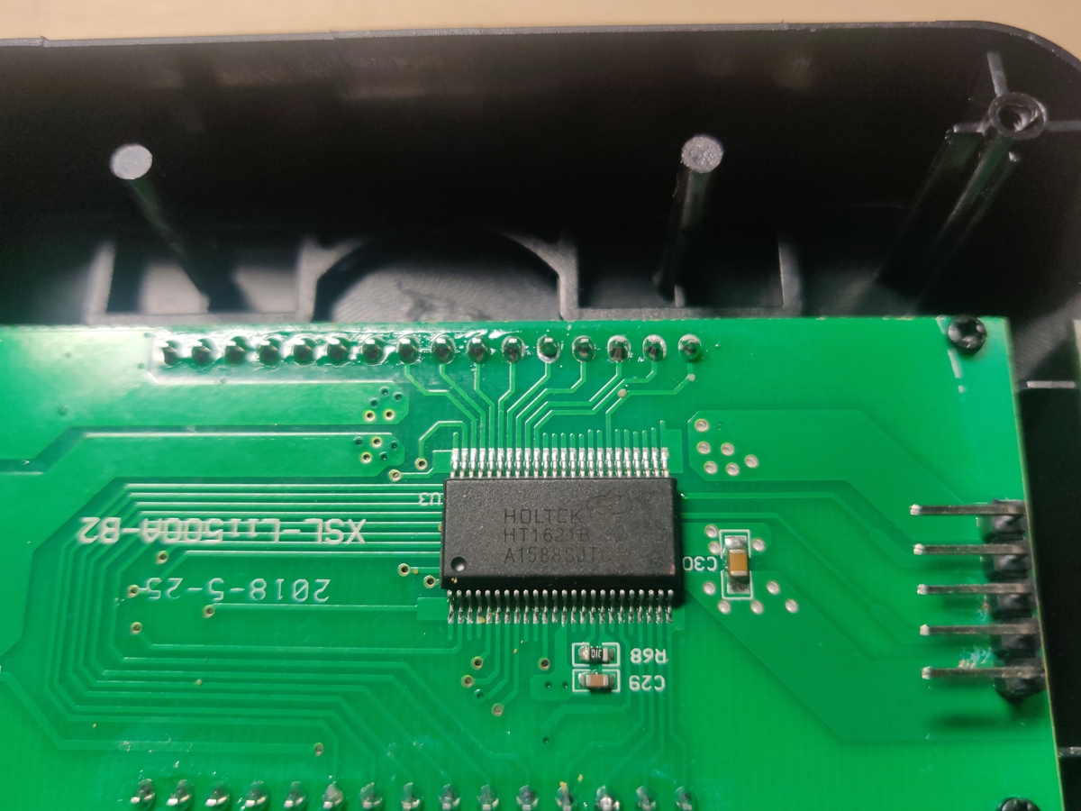
By disassembling the next charger I discovered that it's LCD module contained a marked chip as the LCD controller:
The chip is Holtek 1621B the datasheet is easily found. As I have previously reverse engineered the protocol from scratch I was happy to find that everything matches with what the datasheet describes. The LCD driver chip has much more features than are used by the MCU (for example a watchdog timer). The one interesting tidbit is that the LCD driver chip contains no GPIO pins to drive a transistor controlling the backlight. What the designers choose instead is to reuse the buzzer outputs for the backlight driver. When the LCD backlight enable command is sent the buzzer output is configured to output a 4 kHz tone for the buzzer which I assume drives the backlight transistor.
For posterity I have left all of the reverse-engineering process description in the project details.
 Enki
Enki
Discussions
Become a Hackaday.io Member
Create an account to leave a comment. Already have an account? Log In.