 Greg Zumwalt
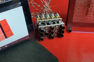
This design uses two cams; one for the segments A, B, G and F (the upper cam), and a second for the segments C, D and E (the lower cam).
The two cams are synchronized by three gears, the center gear being driven by a single inexpensive stepper motor.
The cams are designed to move seven "slides" in a specific sequence in order to produce the displayed digits of 0 through 9. Each cam has one slot for each slide under its control, and a pin on each slide rides in the slot of the cam controlling it. As the cam rotates, the slots induce a linear motion for each slide from 0mm to 3.5mm.
Each of the slides drives a single segment. A pin on the slide fits into a slot on the segment. Slide movement from 0 to 3.5mm induces a rotational movement of the segment of 0 to 90 degrees.


 hugs
hugs

Wow, very cool design with the multiple cam profiles driving it all. And thanks for posting that CAD video, helped me understand how the guts of this work.