 Petar Crnjak
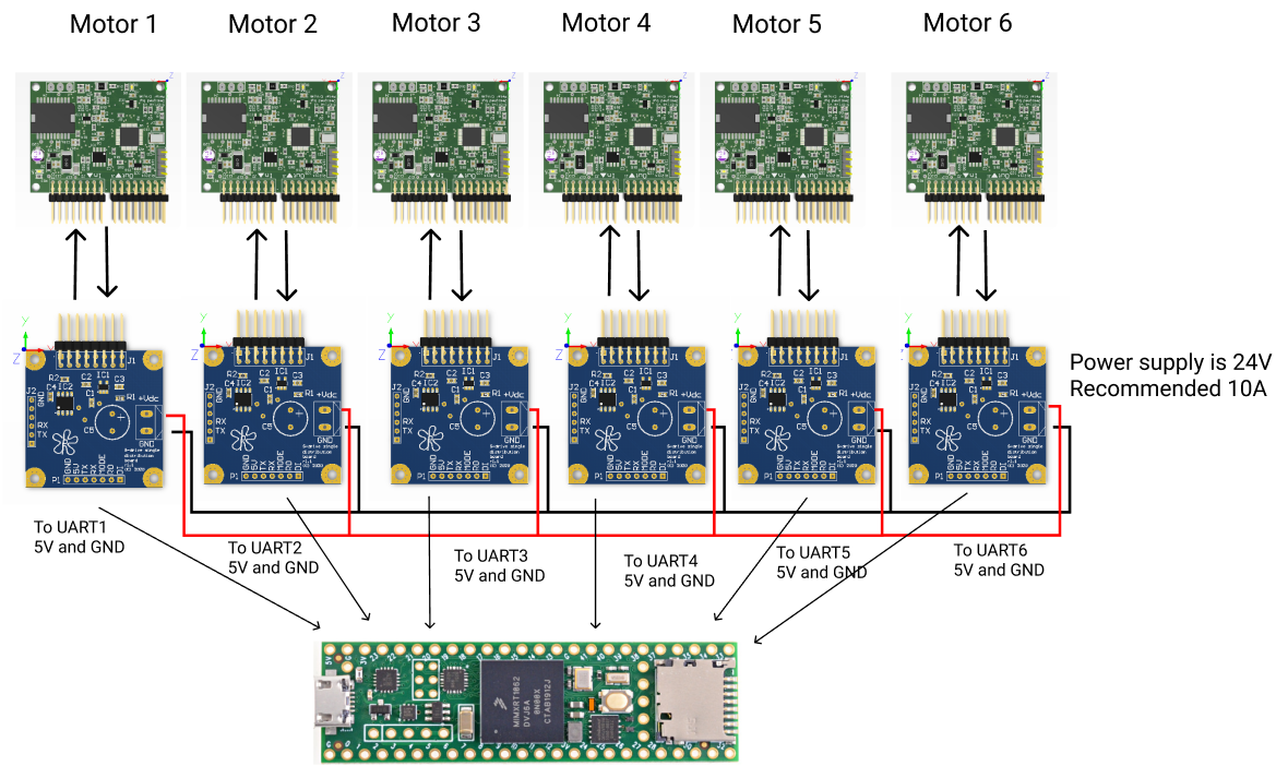
BLDC drivers are connected to connector board using modified IDC cables. More can be found in this folder: https://github.com/PCrnjak/CM6_COBOT_ROBOT under building instructions
- RX1 = PIN0
- TX1 = PIN1
- RX2 = PIN7
- TX2= PIN8
- RX3= PIN15
- TX3 = PIN14
- RX4= PIN16
- TX4 = PIN17
- RX5 = PIN21
- TX5 = PIN20
- RX6 = PIN25
- TX6 = PIN24
Each distribution board is connected to 24V thru screw terminals. Also each distribution board needs to be connected to 5V and GND.
Discussions
Become a Hackaday.io Member
Create an account to leave a comment. Already have an account? Log In.