 Ulrich
So fiannaly after all the component choosing it is the time for a schematic.
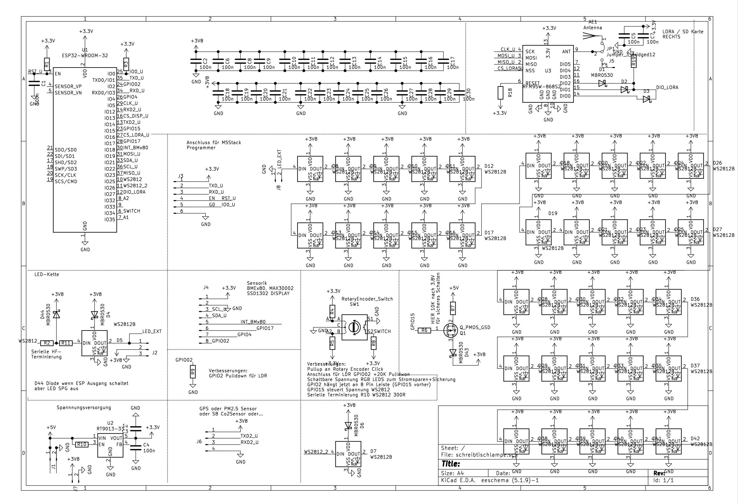
In the past I used KiCad in several other designs. Ist is easy to use and why not use it as well on this design?
In the past I was often searching on my schematics for connections. Thats why I choosed this time to draw logical blocks.
In total we got
- 36 RGB+White LEDs SK6812 or WS2812B (choose which is nicer for you)
- I²C Connector Interface for all kind of Air Quality Sensors
- a LoRa Communication Chip RFM95
- an ESP32 Wroom
- an EC11 Rotary Encoder with built in Switch
- 1 LED RGB for Illumination of the Rotary knob
- a low Dropout Voltage Regulator
- an programming interface
- one more interface for debugging or control even more Air Quality sensors e.g. Sensair S8 or an PM2.5 Sensor.
- Space for an Light Sensor
Schematic V2 with some minor improvements:
Discussions
Become a Hackaday.io Member
Create an account to leave a comment. Already have an account? Log In.